Stator of claw-pole shaped motor
A motor, salient pole type technology, applied in electric components, synchronous motors with stationary armatures and rotating magnets, electromechanical devices, etc. problem, to achieve the effect of increasing the output torque and reducing the distribution of magnetomotive force
- Summary
- Abstract
- Description
- Claims
- Application Information
AI Technical Summary
Problems solved by technology
Method used
Image

Examples
Embodiment 1
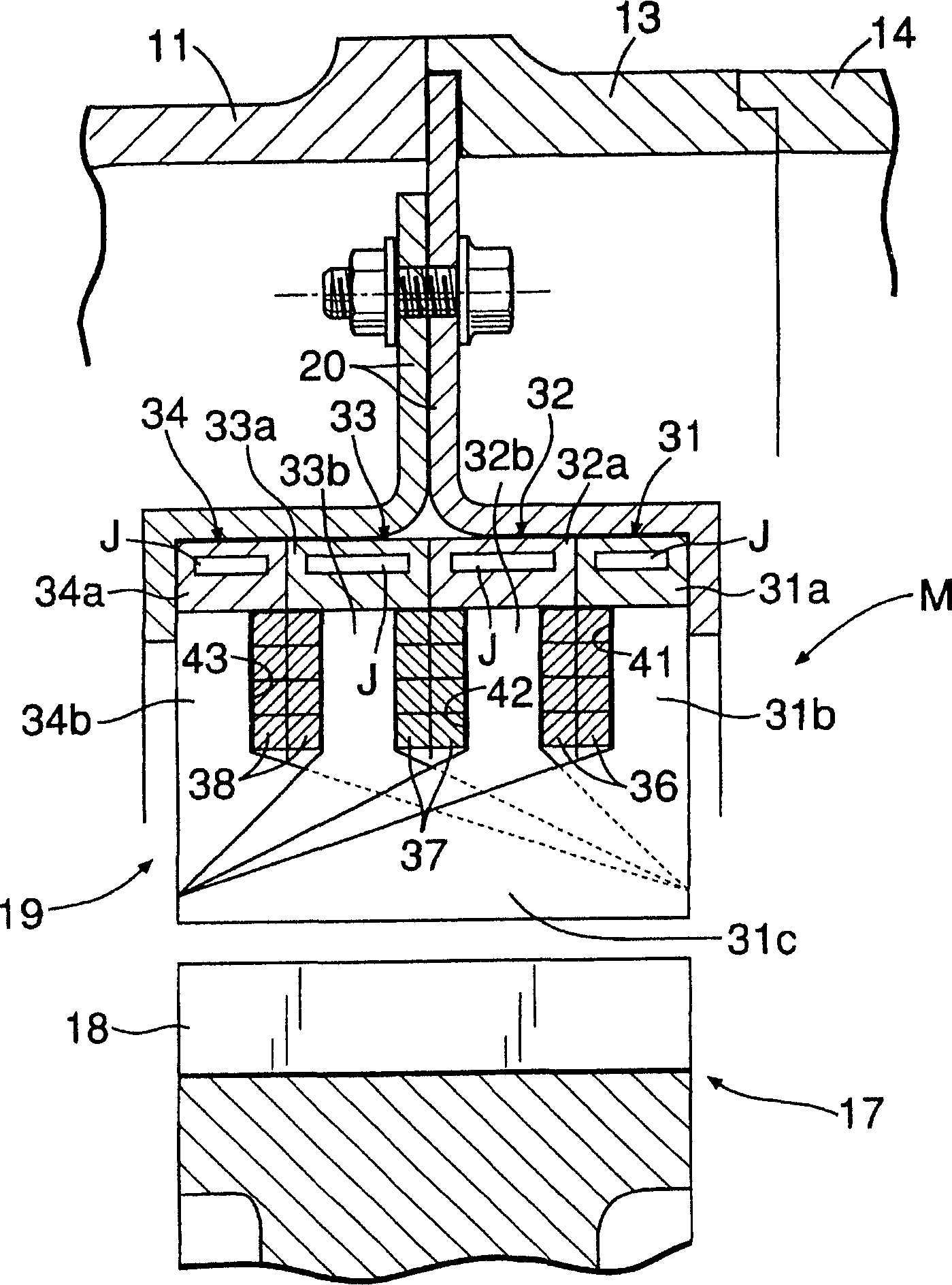
[0082] Figure 27A A magnetic circuit of a conventional m-phase wave winding motor is shown. m is a natural number greater than or equal to 2, and the windings of each phase pass through m staggered slots in a wave shape in such a way that the excitation direction is opposite. At this time, the interlinkage flux of the k-th (1≤k≤m) phase winding is represented by φk-φk+m.
[0083] Figure 9 (A) and (B) represent the magnetic circuit of the m-phase wave-winding salient-pole type motor in which the above-mentioned general m-phase wave-winding motor is developed in the axial direction and provided with 2m teeth and 2m-1 slots. It is known that the interlinkage flux of each phase is constant. That is, the linkage flux of the kth (1≤k≤m-1) phase winding is φk-φ2m-(φk+m-φ2m)=φk-φk+m, and Figure 27A The situation is consistent. In contrast to the case where windings other than the m-th phase exist in two slots, the windings of the m-th phase exist in only one slot.
[0084] Ba...
Embodiment 2
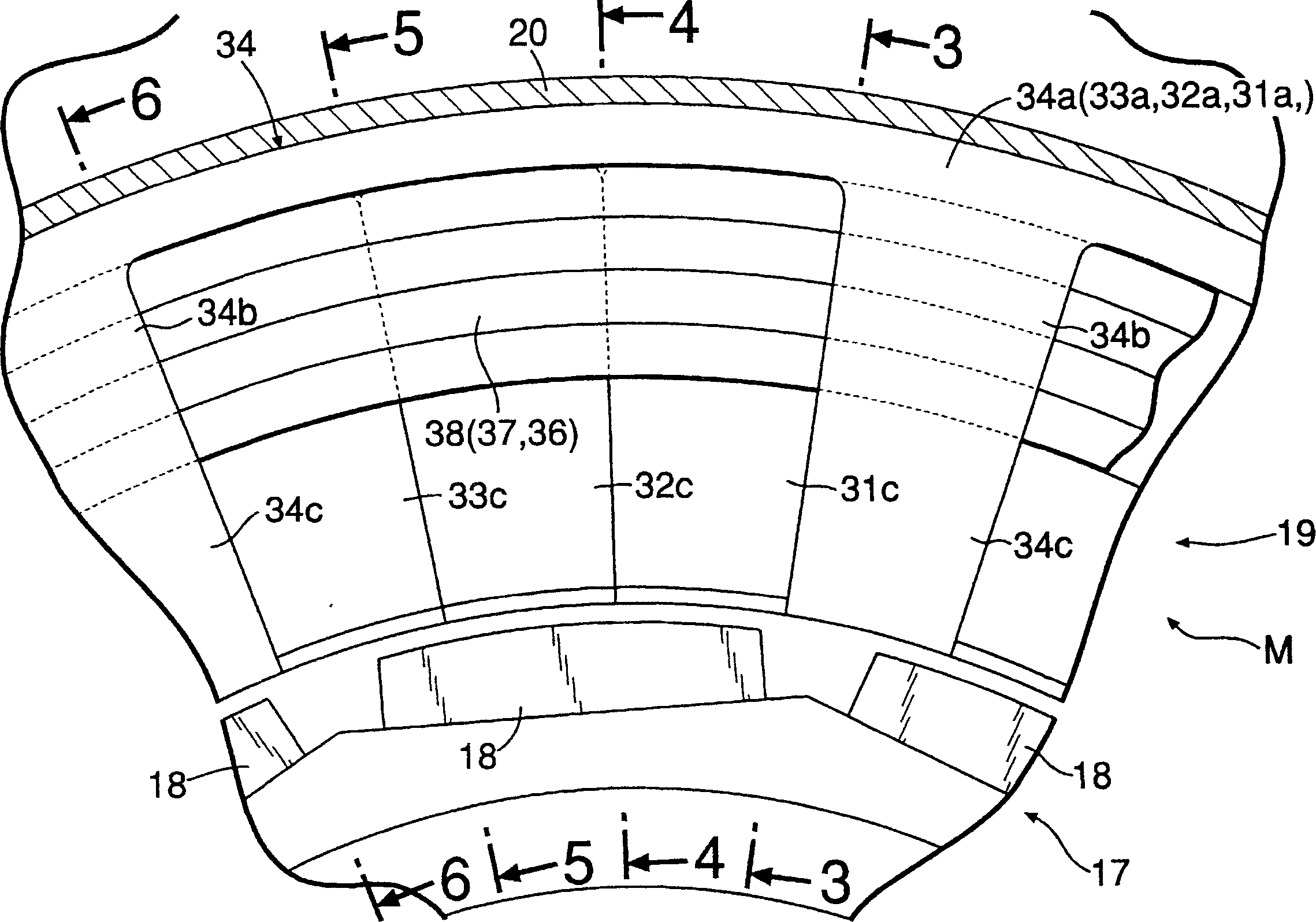
[0105] In the first embodiment, A of the stator 19 + Phase, B + Phase, A - Phase and B - The phase teeth 31b..., 32b..., 33b..., 34b... are arranged so as to be out of phase in the circumferential direction, and the protrusions 31c... , 32c . . . , 33c . . . , 34c . . . have a width equal to the thickness of the stator 19 in the axis L direction. In addition, the width of the permanent magnets 18 of the rotor 17 is equal to the width of the projections 31c..., 32c..., 33c..., 34c..., and the permanent magnets 18 are shared by the projections 31c..., 32c..., 33c..., 34c... of the respective phases. .
[0106] In contrast, in the second embodiment, A of the stator 19 + Phase, B + Phase, A - Phase and B - Phase teeth 31b . . . , 32b . , 33c..., 34c... are also arranged so that the phases are the same. On the other hand, the permanent magnets 18 arranged on the outer periphery of the rotor 17 ... the protrusions 31c ..., 32c ..., 33c ..., 34c ... corresponding to the res...
Embodiment 3
[0110] The third embodiment is a modification of the above-mentioned second embodiment. In the second embodiment, the phases of the protrusions 31c..., 32c..., 33c..., 34c... of each phase are aligned, and the phases of the permanent magnets 18... They are shifted by 360° / 2m=90° respectively. In contrast, in the third embodiment, the phases of the protrusions 31c..., 32c..., 33c..., 34c... of each phase are shifted by 360° / 2m=90°, so that each The phases of the permanent magnets 18 . . . of the phase coincide. Also according to this third embodiment, the same effect as that of the second embodiment can be achieved. And if the permanent magnets 18... are not divided into four stages, and the same permanent magnets 18... as the stator 19 of the first embodiment are used, the number of parts can be reduced.
[0111] Additionally, when Figure 27B shown divided in the circumferential direction Figure 27A In the case of the magnetic circuit of a conventional m-phase wave windin...
PUM
 Abstract
Description
Claims
Application Information
 - Generate Ideas
- Intellectual Property
- Life Sciences
- Materials
- Tech Scout
- Unparalleled Data Quality
- Higher Quality Content
- 60% Fewer Hallucinations
Browse by: Latest US Patents, China's latest patents, Technical Efficacy Thesaurus, Application Domain, Technology Topic, Popular Technical Reports.
© 2025 PatSnap. All rights reserved.Legal|Privacy policy|Modern Slavery Act Transparency Statement|Sitemap|About US| Contact US: help@patsnap.com