Hot-pipe vacuum sealing method and its sealer

A vacuum sealing and heat pipe technology, which is applied to indirect heat exchangers, lighting and heating equipment, etc., can solve the problems of unguaranteed heat pipe packaging quality, waste of packaging materials, and the influence of heat pipe use. The effect of quality improvement

Inactive Publication Date: 2006-11-01
林项武
View PDF0 Cites 10 Cited by
  • Summary
  • Abstract
  • Description
  • Claims
  • Application Information

AI Technical Summary

Problems solved by technology

The productivity is low, and the quality of heat pipe packaging cannot be guaranteed. At the same time, the packaging form of the end not only wastes materials, but also has a certain impact on the use of heat pipes.

Method used


Image

  • Hot-pipe vacuum sealing method and its sealer
  • Hot-pipe vacuum sealing method and its sealer
  • Hot-pipe vacuum sealing method and its sealer

Examples


Embodiment Construction

[0025] Below in conjunction with accompanying drawing and specific embodiment the present invention is described in further detail:

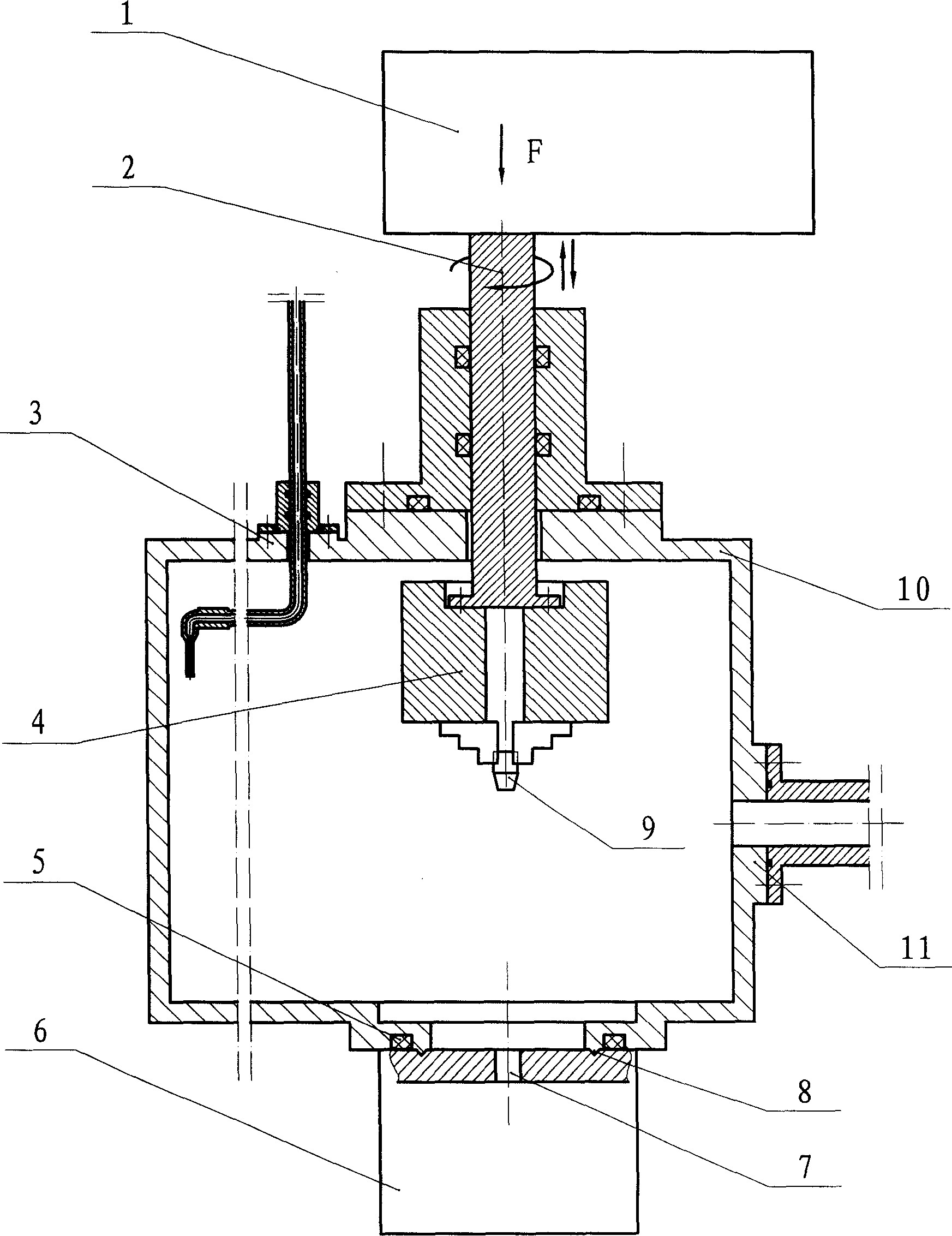
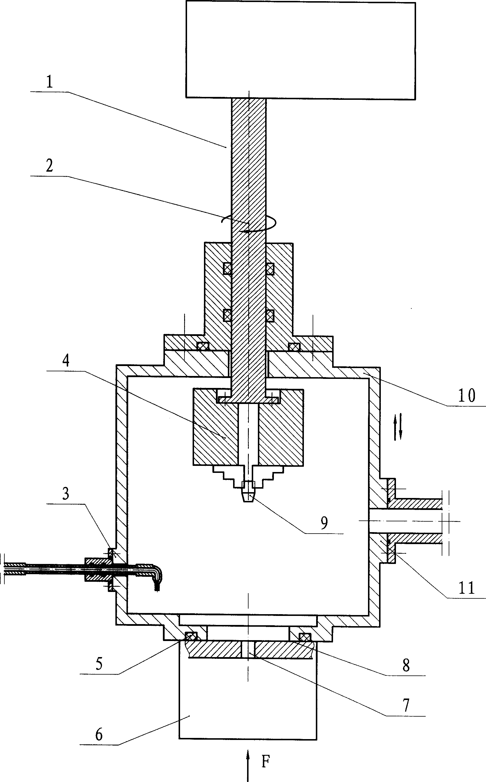
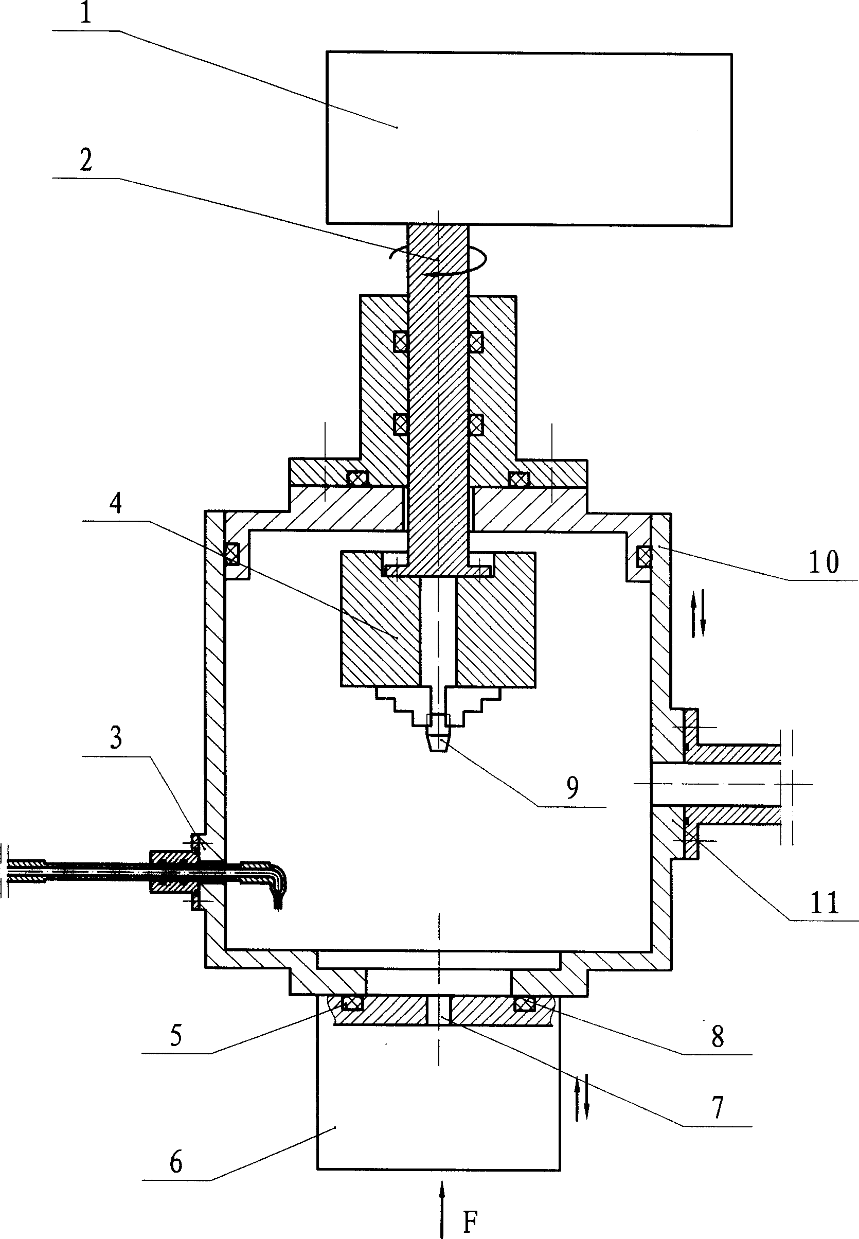
[0026] A heat pipe vacuum sealing method, the heat pipe is packaged after the vacuuming and liquid filling process is completed, the heat pipe 6 to be packaged is reserved with a sealing hole 7, and the sealing hole 7 is contained by a vacuum chamber, and the vacuum chamber is composed of a vacuum container 10 and a heat pipe 6 to be packaged Relying on the vacuum static sealing structure, the vacuum container 10 is provided with a vacuum interface 11 and a liquid filling interface 3, and the vacuuming and liquid filling processes are completed in the vacuum chamber, and the sealing plug 9 is welded to the pre-installed vacuum chamber by friction welding or ultrasonic welding. Stay on the sealing hole 7, and form an airtight weld seam.

[0027] In the heat pipe vacuum sealing method, the sealing plug 9 can be one of a cylinder, a cone, a T-shape...


PUM


Abstract

The invention comprises a vacuum-producing system, an awaiting seal heat-pipe, a position clamping system and a charging system. The awaiting seal heat-pipe is fixed via the position clamping system. The future sealing holes of the awaiting seal heat-pipe are held in a vacuum cavity consisting of the vacuum container with vacuum-pumping and charging interfaces. After finishing the process of vacuum-pumping and charging in the vacuum cavity, the clamping system holds the sealing plug to the sealing hole, a friction welding system or an ultrasonic welding system will finish soldering and sealing of the future sealing holes of the awaiting seal heat-pipe and the sealing plug.

Description

technical field [0001] The invention relates to a heat pipe vacuum sealing method and device, in particular to a sealing method and device for heat exchange equipment utilizing an intermediate heat transfer medium or an intermediate heat transfer body. Background technique [0002] "Heat Pipe Technology and Its Engineering Application" (ISBN 7-5025-2752-4 / TQ.1212) describes several commonly used heat pipe vacuum sealing methods and devices. The method is to vacuumize the reserved seal of the heat pipe to be packaged through the capillary, inject the working medium after reaching the vacuum degree required by the process, and immediately flatten the capillary to seal, and then weld. The heat generated during the welding process of heat pipes using non-metallic working medium can easily cause the non-metallic working medium to exceed its decomposition temperature, produce non-condensable gas, and even make the heat pipe scrapped. The productivity is low, and the quality of he...

Claims


Application Information

Patent Timeline
Patent Type & Authority Applications(China)
IPC IPC(8): F28D15/02
Inventor 林项武
Owner 林项武
Why Eureka
Try Eureka