
Drive control apparatus for magnetic stepping motor and sewing machine

A stepping motor and driven technology, which is applied in the direction of program-controlled sewing machines, motor generator control, control systems, etc., can solve the problem of not being able to reliably prevent pattern deformation

Active Publication Date: 2006-11-01
BROTHER KOGYO KK
View PDF0 Cites 9 Cited by
  • Summary
  • Abstract
  • Description
  • Claims
  • Application Information

AI Technical Summary

Problems solved by technology

There is a problem that the pattern deformation cannot be reliably prevented

Method used


Image

  • Drive control apparatus for magnetic stepping motor and sewing machine
  • Drive control apparatus for magnetic stepping motor and sewing machine
  • Drive control apparatus for magnetic stepping motor and sewing machine

Examples


Embodiment Construction

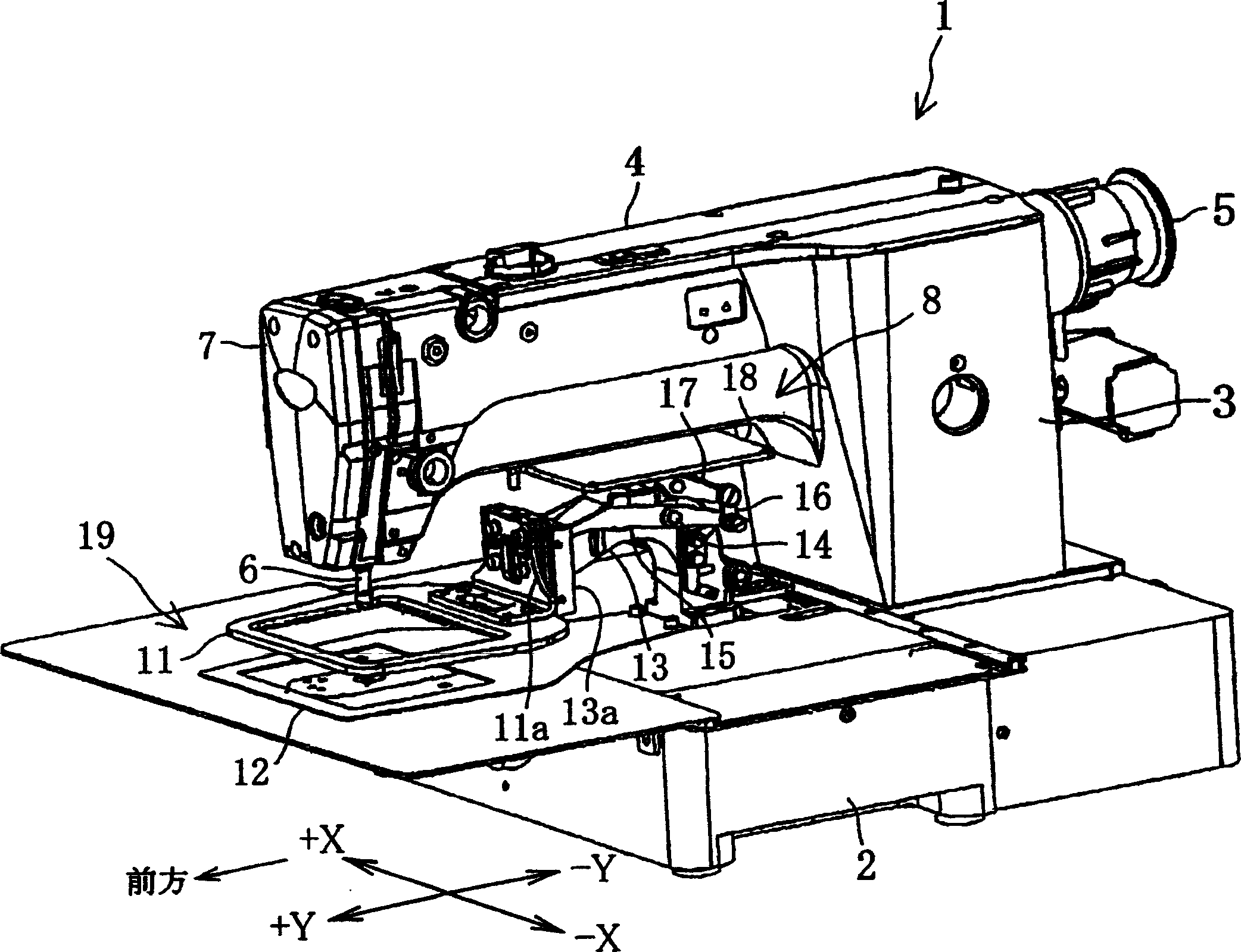
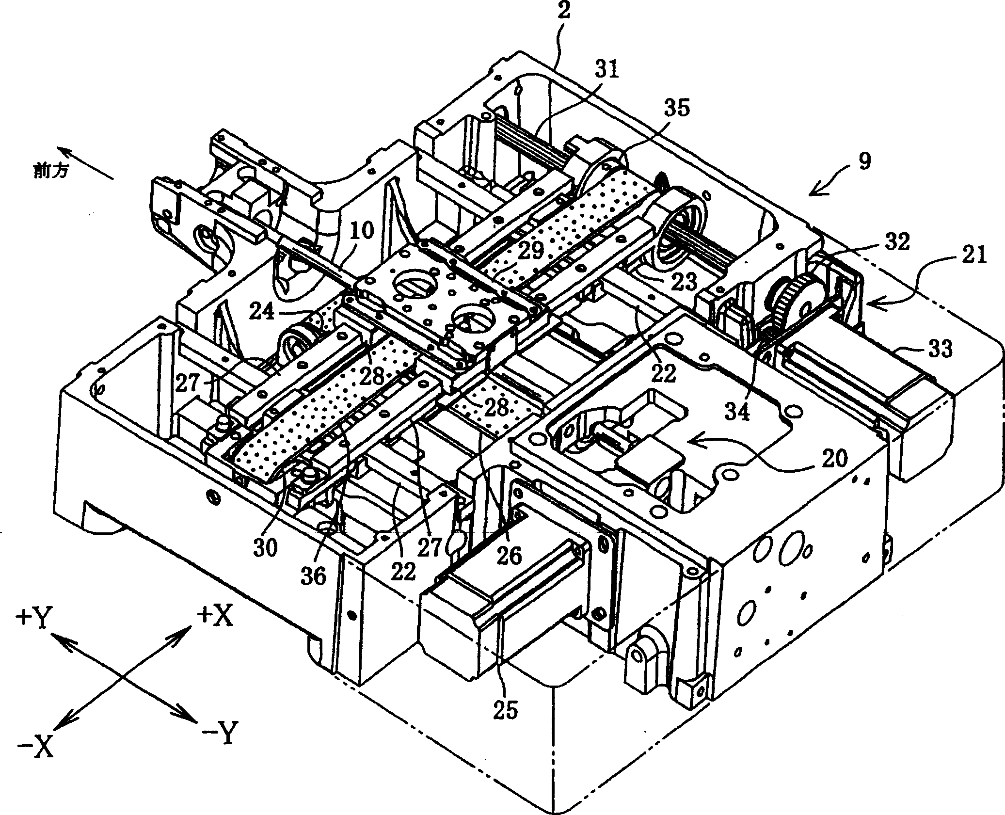
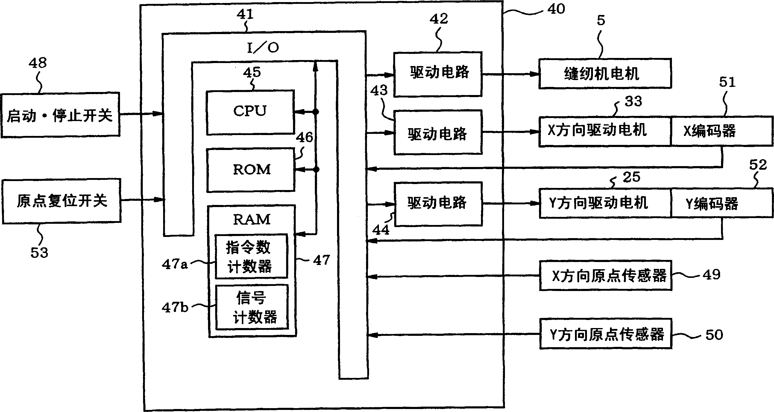
[0020] In order to explain this invention in detail, it demonstrates referring drawings. Figure 1 to Figure 5 An example in which the present invention is applied to a fancy knotting sewing machine is shown.

[0021] Such as figure 1 As shown, the fancy knotting sewing machine 1 has: a base part 2, a column part 3 erected from the rear end part of the base part 2, and a front side facing the base part 2 from the upper end part of the column part 3. Extended arm section 4.

[0022] A sewing machine motor 5 and a driving force transmission mechanism (not shown) for transmitting the driving force of the sewing machine motor 5 to the needle bar 6 via the main shaft are provided in the column portion 3 and the machine arm portion 4 . A needle bar up and down movement mechanism (not shown) for moving the needle bar 6 up and down is provided at the front end of the machine arm part 4 , that is, inside the machine head 7 . By driving the sewing machine motor 5, the sewing needle m...


PUM


Abstract

The drive control device of the stepping motor of the present invention feedback-controls the stepping motor according to the coded signal output by the encoder, and is characterized in that it is provided with: a counter for the number of instructions, through which the number of driving pulses given to the stepping motor Counting is performed to obtain a count value of the number of instructions; a signal counter is used to obtain a signal count value by counting the number of pulses of the encoded signal; During the specified action, when the hysteresis state occurs where the count value of the instruction count is inconsistent with the count value of the signal × C (C is a predetermined positive constant), the stepping motor is operated in a specific mode of operation. The driven system is driven down, and the hysteresis of the driven system is eliminated.

Description

(1) Technical field [0001] The present invention relates to a drive control device for a stepping motor and a sewing machine capable of eliminating hysteresis in the driven system when the driven system is driven and controlled by a stepping motor. (2) Background technology [0002] In the past, when driving various driven systems, stepper motors (pulse motors) capable of open-loop drive control were mostly used. For example, in electronic sewing machines, small and easy-to-control stepping motors are used in the needle swing mechanism that swings the needle bar, and the cloth feed drive mechanism that feeds the processed cloth through the feed dog and the cloth holder. [0003] When the cloth feeding operation is performed by moving the feeding dog and the cloth holding frame, if the load of the stepping motor is large, the load will affect the number of driving pulses (command pulses) given to the stepping motor by the control device and the rotation of the stepping motor....

Claims


Application Information

Patent Timeline
IPC IPC(8): H02P8/14D05B19/12D05B19/16D05B21/00
Inventor 青木信吉田信次竹村彻
Owner BROTHER KOGYO KK
Learn More