Method for controlling and/or adjusting a welding process

A welding process and mechanical adjustment technology, applied in welding equipment, manufacturing tools, arc welding equipment, etc., can solve the problem that the distance between the end of the welding wire and the workpiece cannot be accurately determined, and achieve high accuracy

Active Publication Date: 2006-11-01
FRONIUS INTERNATIONAL GMBH
View PDF1 Cites 10 Cited by
  • Summary
  • Abstract
  • Description
  • Claims
  • Application Information

AI Technical Summary

Problems solved by technology

However, the above-mentioned invention includes the following disadvantages: the distance between the end of the welding wire and the workpiece cannot be accurately determined because of the many different influencing factors encountered in the welding process

Method used


Image

  • Method for controlling and/or adjusting a welding process
  • Method for controlling and/or adjusting a welding process
  • Method for controlling and/or adjusting a welding process

Examples


Embodiment Construction

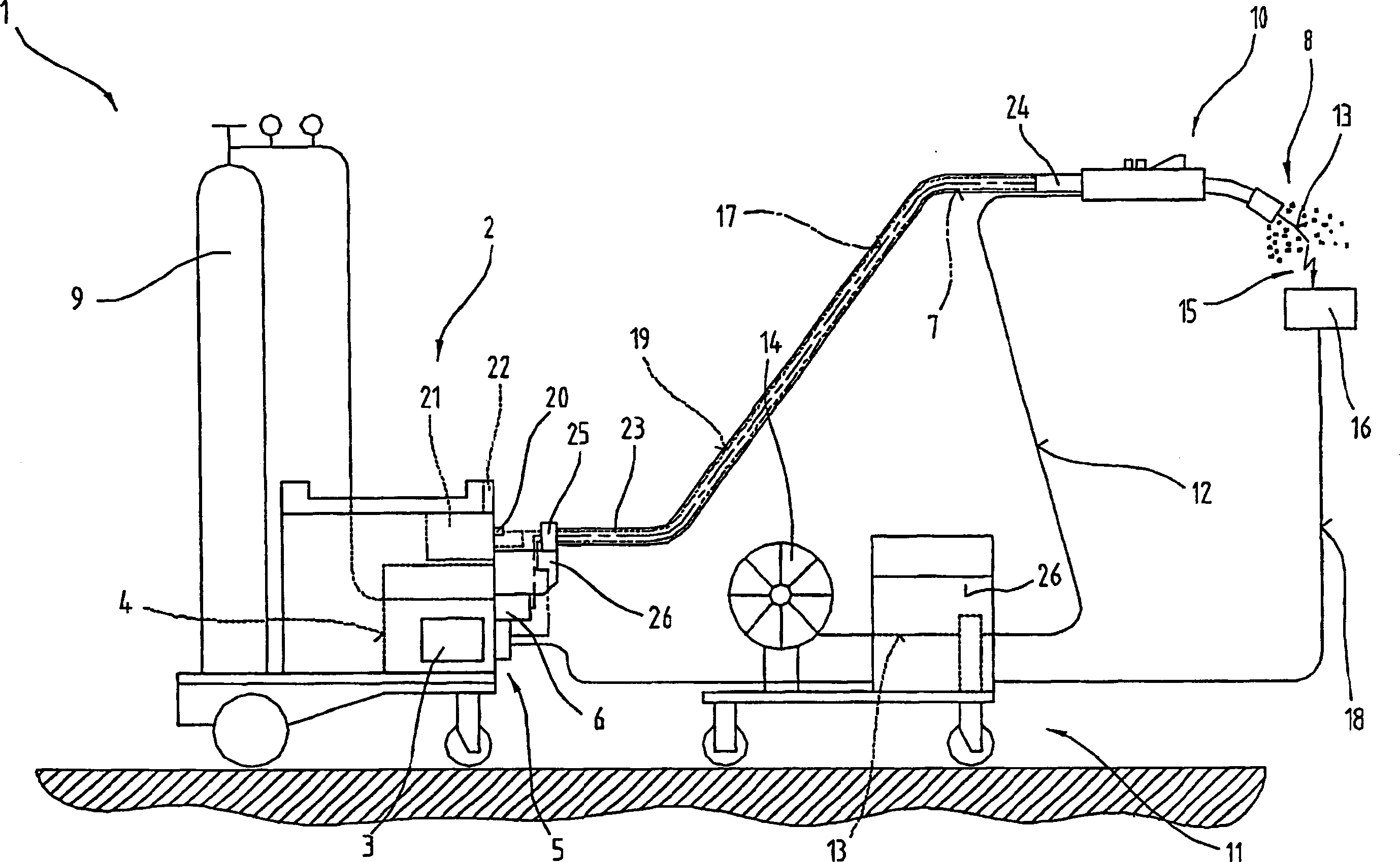
[0025] figure 1 A welding apparatus 1 or welding structure is shown for various processes or methods such as MIG / MAG welding or WIG / TIG welding, or electrode welding methods, twin wire / tandem multi-arc welding methods, plasma welding or brazing method etc.

[0026] The welding device 1 comprises a power source 2 comprising a power element 3 , a control device 4 and a switching element 5 , and the switch element 5 is connected to the power element 3 and the control device 4 respectively. The switching element 5 and the control device 4 are connected to a control valve 6 arranged in a supply line 7 between the gas tank 9 and the welding torch 10 or torch for the gas 8 and, in particular, for protection Inert gases, such as carbon dioxide, helium or argon, etc.

[0027] In addition, a wire feeder 11 commonly used in MIG / MAG welding can be controlled by the control device 4 whereby additional material or welding wire 13 is supplied from a supply drum 14 or wire coil via a supply...


PUM


Abstract

The invention relates to a method for controlling and/or adjusting a welding process, using a melting welding wire (13), wherein after ignition of an electric arc, a welding process is carried out , said welding process being adjusted on the basis of several different welding parameters and being controlled or adjusted by a control device and/or a welding current source. In order to determine the position or distance between the end of the welding wire (13) and the workpiece (16), which is to be processed, in a manner which is as accurate as possible, at least one mechanical adjustment process (41) is carried out during the welding process, enabling the position of said welding wire (13) to be determined, said welding wire (13) being used as a sensor.

Description

technical field [0001] The invention relates to a method for controlling a welding process, wherein after ignition of the arc, a welding process is carried out which is adjusted on the basis of several different welding parameters and controlled by a control device and / or a welding power source. Background technique [0002] Patent Publication EP0774317B1 discloses a pulsed arc welding method for alternately supplying a pulse current and a base current through a consumable electrode and a base metal, respectively. In this method, the length of the arc is controlled in such a way that the average or cumulative value over time corresponds to a set value. The base current decreases with a higher time-averaged or accumulated value and increases with a smaller value. In addition, the supply time of the pulse and base currents can be decreased or increased according to the measured length of the arc. Typically, the length of the arc and thus the distance between the wire end and...

Claims


Application Information

Patent Timeline
Patent Type & Authority Applications(China)
IPC IPC(8): B23K9/12
CPCB23K9/125B23K9/0735
Inventor 约瑟夫·阿特尔斯梅尔
Owner FRONIUS INTERNATIONAL GMBH
Why Eureka
Try Eureka