
Method and installation for extracting energy from a flowing fluid

A fluid and energy technology, applied in the field of turbine farms, which can solve the problems of increasing fluctuating loads, and achieve the effects of low axial induction, reduced wake loss, and small chord characteristics

Active Publication Date: 2006-11-01
NEDERLANDSE ORG VOOR TOEGEPAST-NATUURWETENSCHAPPELIJK ONDERZOEK (TNO)
View PDF1 Cites 7 Cited by
  • Summary
  • Abstract
  • Description
  • Claims
  • Application Information

AI Technical Summary

Problems solved by technology

As turbulence increases, fluctuating loads on the turbine increase, which is a disadvantage

Method used


Image

  • Method and installation for extracting energy from a flowing fluid
  • Method and installation for extracting energy from a flowing fluid
  • Method and installation for extracting energy from a flowing fluid

Examples


Embodiment Construction

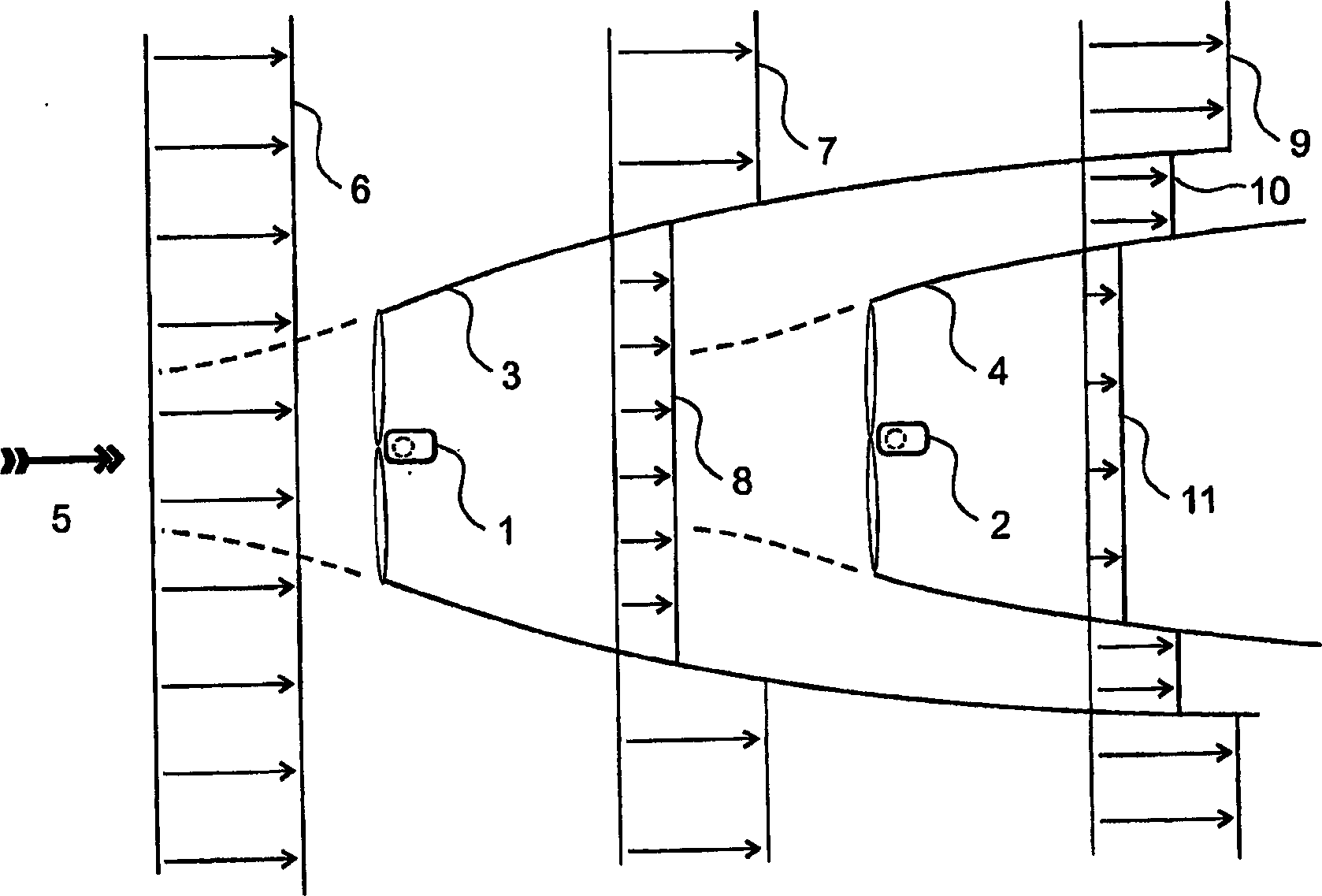
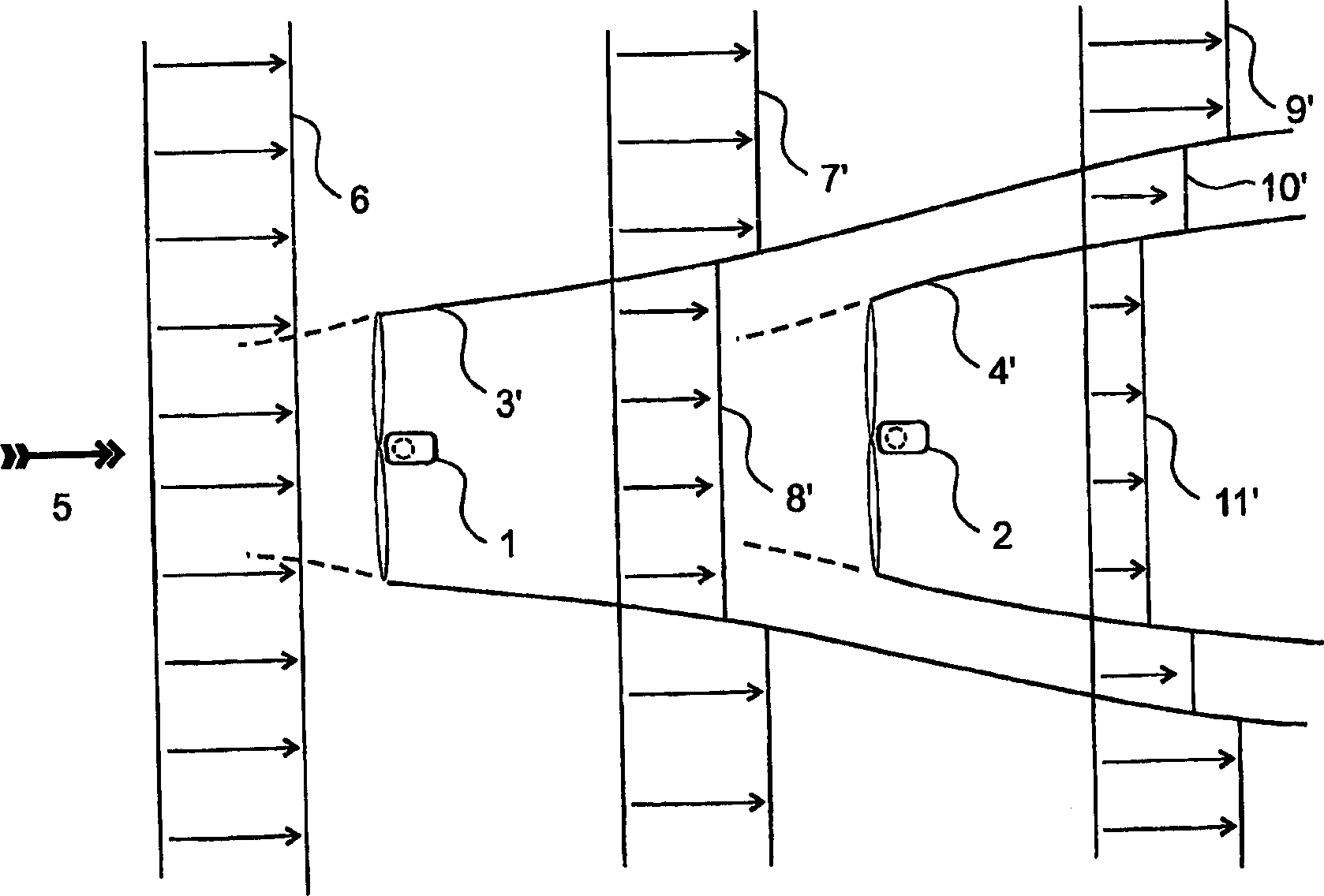
[0058] figure 1 A small wind farm with only two wind turbines, the first turbine 1 and the second turbine 2, can be seen in .

[0059] The wind force 5 has a given intensity and direction as indicated by the arrow 5 . In this particular case, the direction is parallel to the line formed by the front turbine 1 to the rear turbine 2 .

[0060] exist figure 1 In , a sketch is designed for a situation where the first turbine 1 extracts the most energy from the wind, ie theoretically at 1 / 3 axial induction (approximately 0.28 in practice).

[0061]The wind 5 has a uniform velocity distribution (6) before passing the first turbine 1 . After passing through the first turbine 1, the speed of the wind 5 blowing through the turbine is generally reduced, which can be seen from the uniform velocity distribution 6 after passing through the turbine 1 into the wind speed distribution 7, 8, wherein the central part of the distribution 8 generally designates decelerated wake air that sprea...


PUM


Abstract

Turbine farm comprising at least a first turbine (1) and at least a second turbine (2) by means of which energy can be extracted from a flowing fluid, wherein when the second turbine is on the lee side of the first turbine, under nominal power, the axial induction of the first turbine is lowered with respect to the second turbine, to reduce turbulence mainly at the location of the at least second turbine.

Description

technical field [0001] The invention relates to a turbine farm according to the preamble of claim 1 . The invention also relates to a method for such a turbine farm. Furthermore, the invention relates to a control system and a control system program for implementing the method. [0002] More generally, the present invention relates to methods and / or apparatus that can extract energy from flowing fluids. The term flowing fluid is used to refer to wind and moving (sea) water. A plant is understood to mean a turbine system (in particular a wind farm) with a control system. Background technique [0003] It is well known that wind turbines can be used to extract energy from the wind. [0004] The size and number of wind turbines have increased rapidly in recent years. It is increasingly common for several turbines to be installed next to each other in so-called wind farms. Because of the scarcity of space on land (especially in Europe), turbines are increasingly being insta...

Claims


Application Information

Patent Timeline
Patent Type & Authority Applications(China)
IPC IPC(8): F03D11/04F03B15/06F03D7/04
CPCF03B15/06F03D7/0292F03D7/048F05B2240/96F05B2270/20F05B2270/321Y02E10/20F05B2270/204Y02E10/72F03D7/04
Inventor 古斯塔夫·P·科尔滕彼得·沙克
Owner NEDERLANDSE ORG VOOR TOEGEPAST-NATUURWETENSCHAPPELIJK ONDERZOEK (TNO)
Learn More