Evacuable flat panel solar collector

A flat-panel solar energy and collector technology, applied in the directions of solar thermal collectors, solar thermal collector safety, solar thermal collectors using working fluid, etc., can solve problems such as the inability to eliminate molecular conduction.

Inactive Publication Date: 2006-11-01
EUROPEAN ORGANIZATION FOR NUCLEAR RESEARCH
View PDF8 Cites 13 Cited by
  • Summary
  • Abstract
  • Description
  • Claims
  • Application Information

AI Technical Summary

Problems solved by technology

Therefore, planar solar collectors can only be evacuated to 1 Torr, which is sufficient to eliminate air convection but not molecular conduction

Method used


Image

  • Evacuable flat panel solar collector
  • Evacuable flat panel solar collector
  • Evacuable flat panel solar collector

Examples


Embodiment Construction

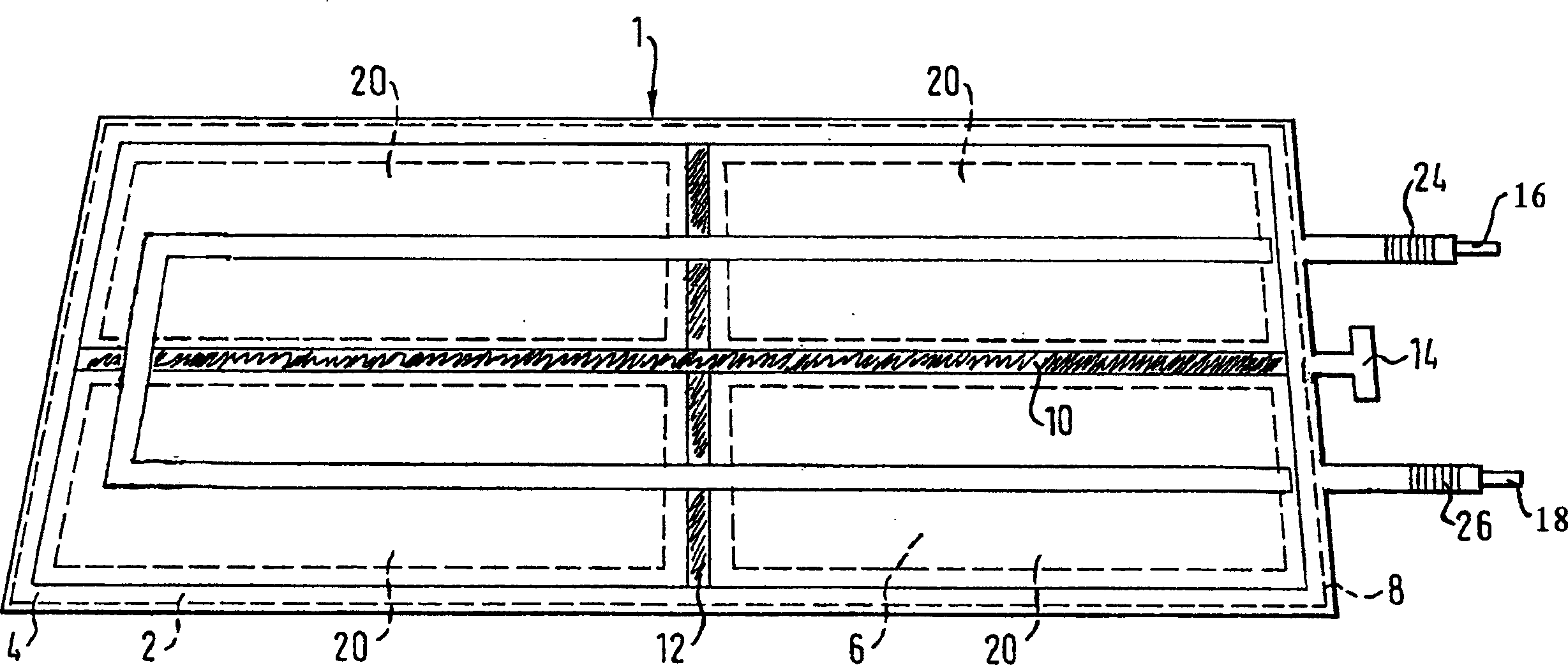
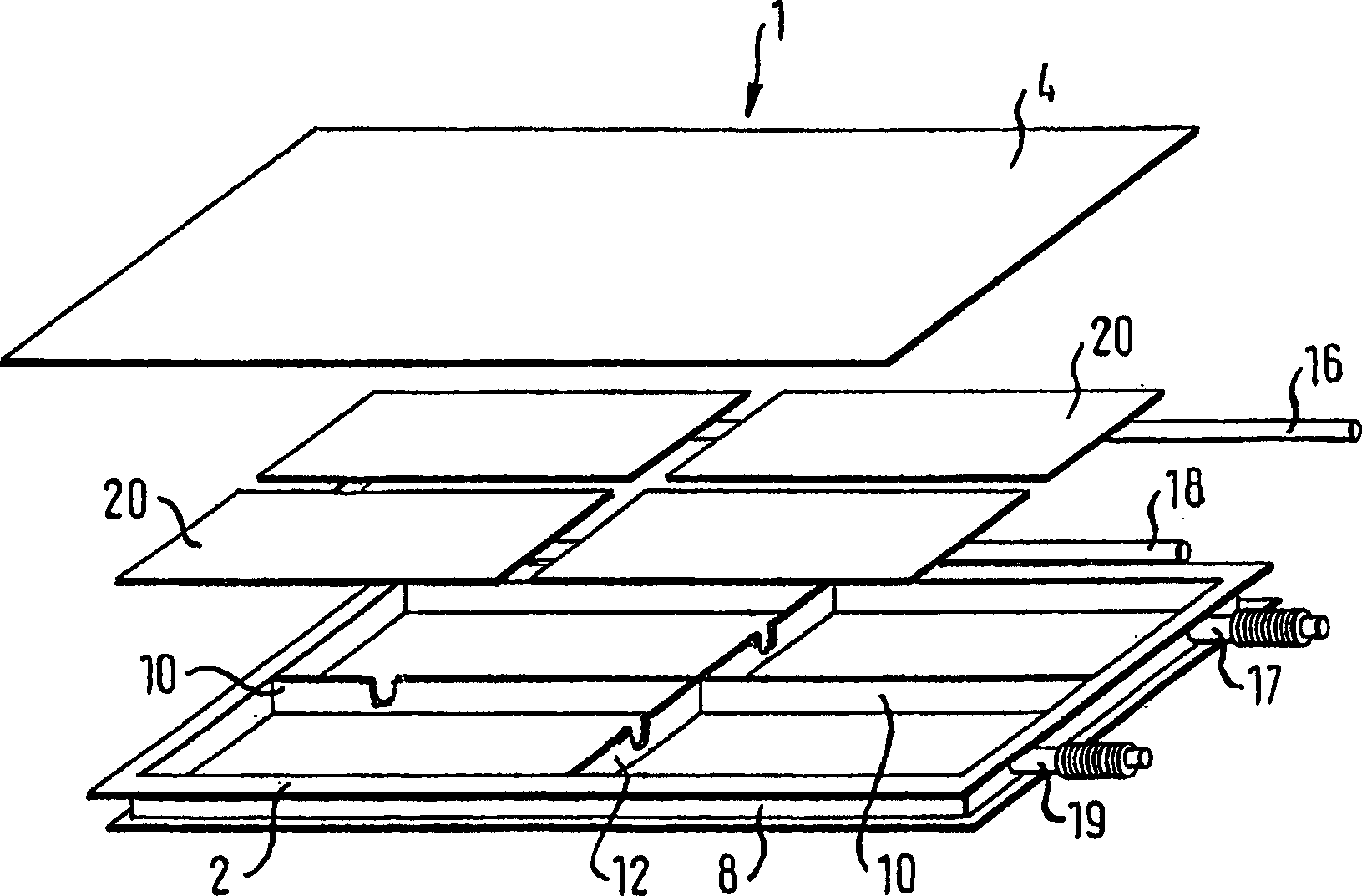
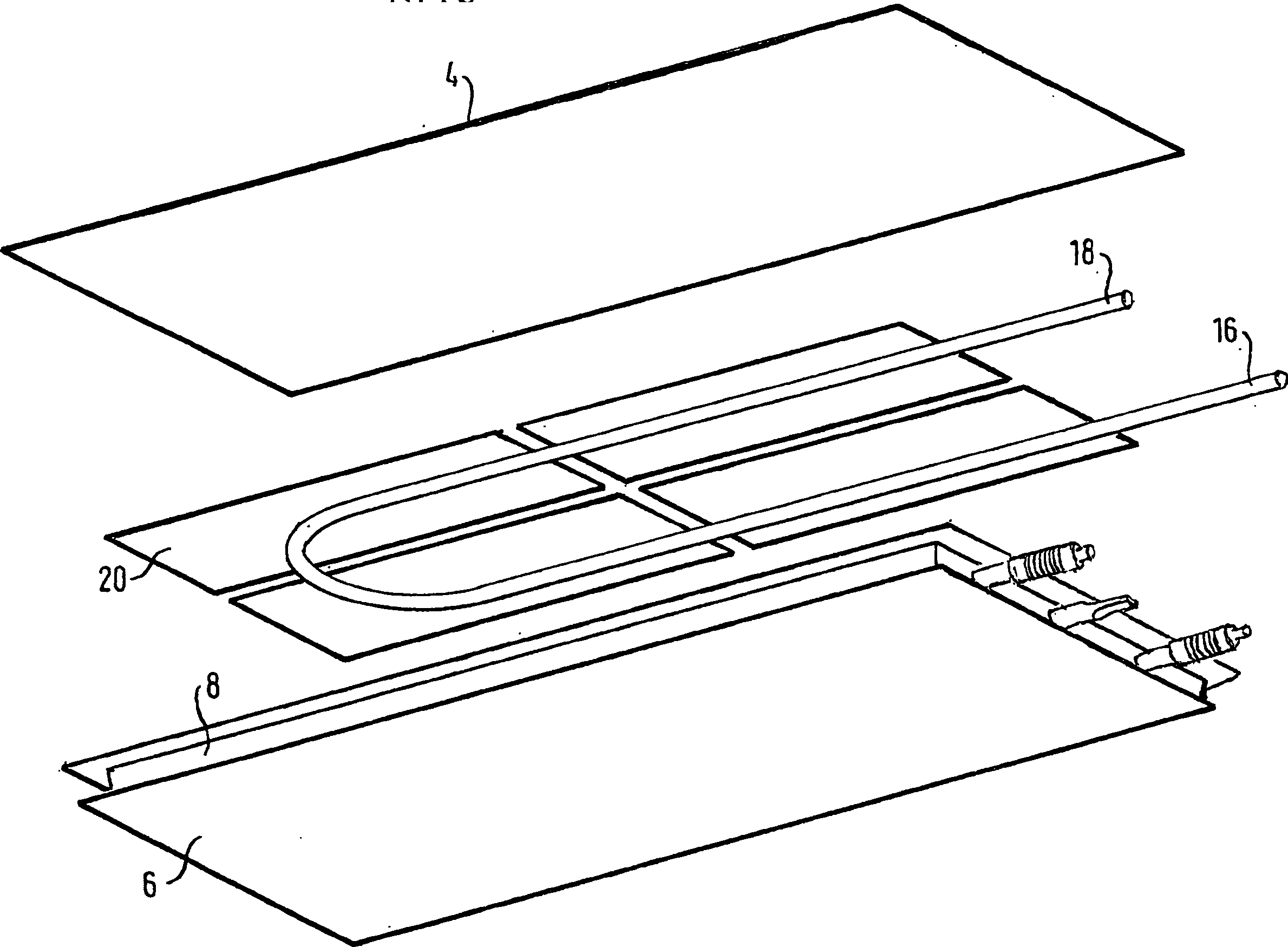
[0068] exist Figure 1a In , a flat panel solar collector 1 is shown, which is rectangular in shape and comprises a housing 2 in the form of a metal box and a flat wall 4 with a transparent top. The housing 2 comprises a substantially flat bottom 6 and peripheral side frames 8 . The top transparent flat wall 4 is arranged on the frame 8 along its circumference. Longitudinal and transverse metal bars 10 and 12 are used as spacers to support the transparent flat wall 4 . A low pressure can be established inside the flat panel solar collector 1 via the connection opening 14 , which represents a lateral connection through the frame 8 into the housing 2 . Ducts or cooling pipes 16 and 18 are arranged inside the housing, preferably between the bottom 6 and the plate absorber 20 (shown in dashed lines to show the cooling ductwork beneath it). The sunlit surface of the absorber 20 is preferably coated with a black film. Furthermore, the cooling pipes 16 and 18 are thermally connect...


PUM


Abstract

The present invention relates to an evacuable flat panel solar collector (1) wherein the transparent planar wall (4) and the housing (2) are sealed by a soft metal ribbon (32) which is soft soldered at least with a first portion (34) to the housing (2) and at least with a second portion (36) to a metallized area of the transparent planar wall (4). The present invention also relates to a method for the preparation of said flat panel solar collectors (1) as well as to a flat panel solar collector system (56) comprising said flat panel solar collector (1) and at least one external mirror (54).

Description

technical field [0001] The invention relates to an easily drainable flat panel solar collector comprising at least one absorber, at least one duct, a holding structure and at least one transparent wall. The invention also relates to a flat-panel solar collector system comprising at least one flat-panel solar collector according to the invention and at least one reflector. The invention also relates to a flat panel solar collector array. Finally, the invention relates to a method for manufacturing an easily drainable flat panel solar collector according to the invention. Background technique [0002] Solar collectors, in particular flat panel solar collectors, are well known devices which are commonly used to absorb solar energy and transfer it into a collection fluid. Primarily, the solar collector consists of a blackened absorbing cylinder or panel housed in an enclosure closed from the front by a transparent glass panel. Due to the debilitating nature of sunlight, in or...

Claims


Application Information

Patent Timeline
Patent Type & Authority Applications(China)
IPC IPC(8): F24J2/50F24J2/46F24S10/40F24S10/70F24S10/75F24S23/70F24S23/74
CPCF24S10/40F24S10/755F24S23/74F24S23/80F24S40/46F24S80/453F24S80/54F24S80/58F24S80/70F24S2025/011F24S2025/6013Y02E10/44Y10S126/908Y02E10/40
Inventor 克里斯托福洛·本韦努蒂
Owner EUROPEAN ORGANIZATION FOR NUCLEAR RESEARCH
Why Eureka
Try Eureka