Method and device for the determination of the actual position of a geodesic instrument

A technology of actual position and geodetic measurement, applied in the direction of measuring instruments, measuring devices, instruments, etc., can solve problems such as adverse effects of the measurement process

Inactive Publication Date: 2006-11-01
LEICA GEOSYSTEMS AG
View PDF3 Cites 9 Cited by
  • Summary
  • Abstract
  • Description
  • Claims
  • Application Information

AI Technical Summary

Problems solved by technology

Self-conscious position changes between known points also have a detrimental effect on the measuring process

Method used


Image

  • Method and device for the determination of the actual position of a geodesic instrument
  • Method and device for the determination of the actual position of a geodesic instrument
  • Method and device for the determination of the actual position of a geodesic instrument

Examples


Embodiment Construction

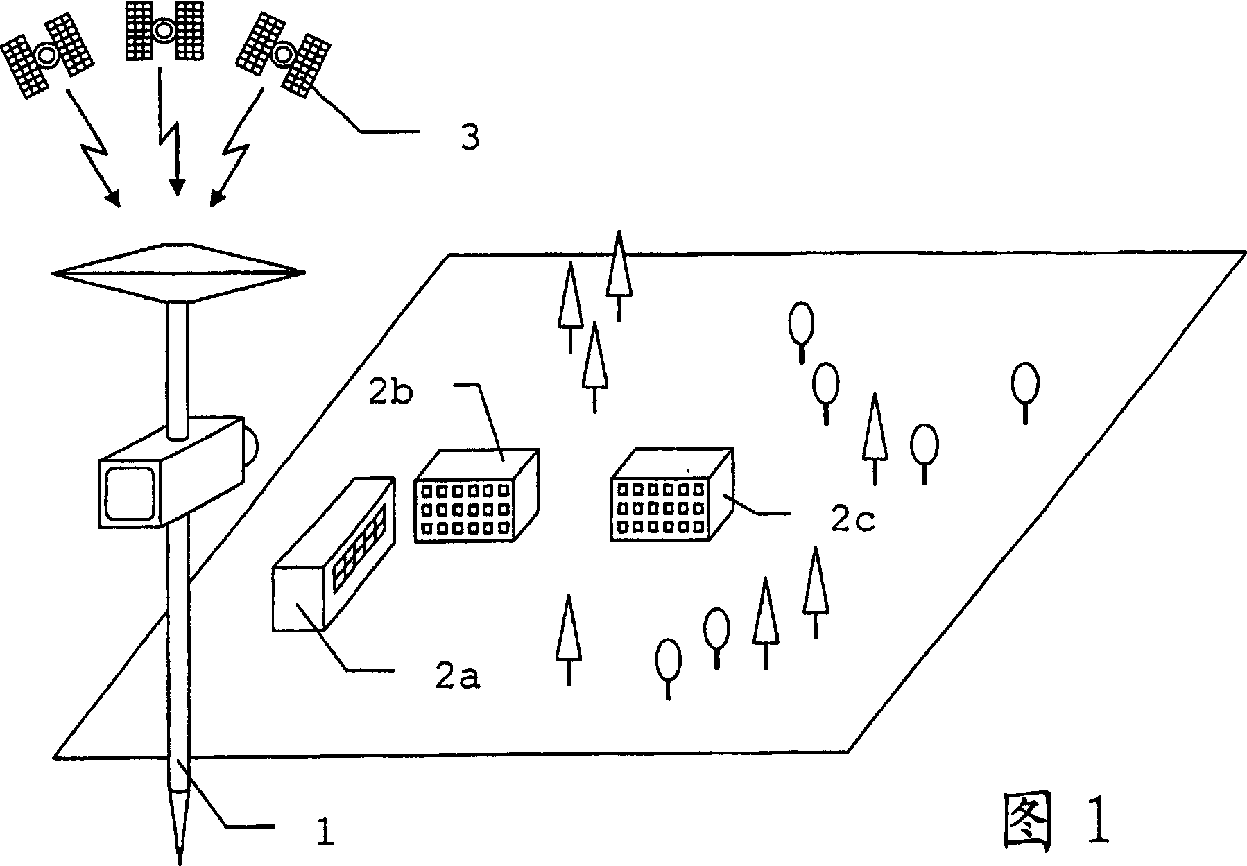
[0045] Figure 1 shows a typical survey task using a positioning system. The purpose of the survey is to determine the position of various points on the object 2c arranged in the complex together with the auditorium 2a and the building 2b. The surveying is carried out using a geodetic instrument 1 which has the components required for the respective surveying task. The actual position of the instrument 1 can be determined on the basis of signals of a positioning system, which is here assumed to be a satellite-supported system purely by way of example, representing in each case the current position to be determined for the survey. The actual position can be derived from the signal of the satellite 3, which is received by the satellite receiver of the instrument 1 and which travels substantially in a straight line.

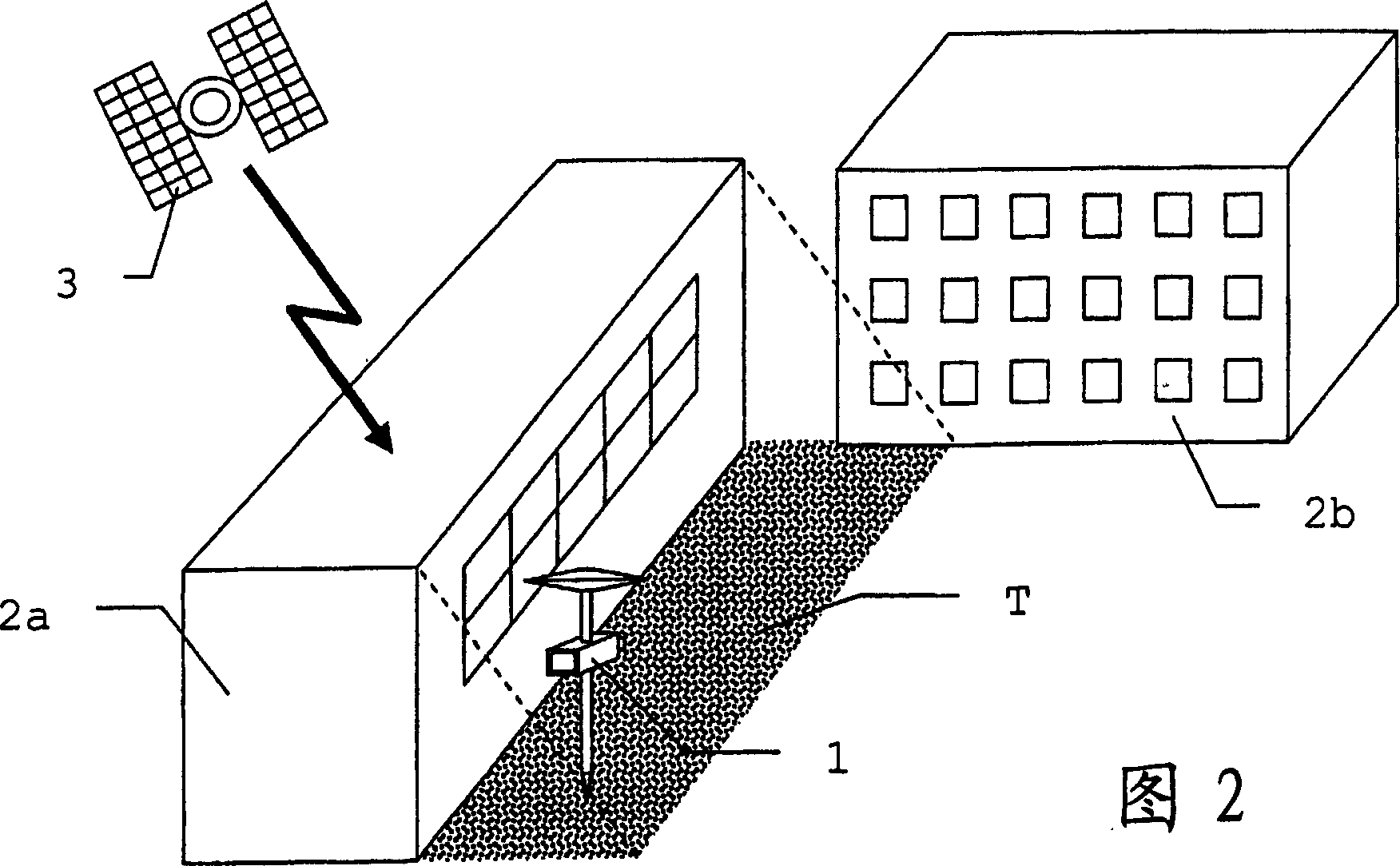
[0046] FIG. 2 schematically shows the situation in the immediate vicinity of the object to be surveyed. If for survey purposes it is necessary to place the instrum...


PUM


Abstract

In order to determine the actual position (A) of a geodetic measuring instrument (1) inside a dead range (T) wherein signals originating from a positioning system are shadowed, two reference structures (5) are detected from at least two known positions and the distances associated with the reference structures (5) are measured. Image information linked to said distance measurements is captured. Said information contains data on the arrangement of the reference structures (5). The actual position (1) can be derived from subsequent capture of the reference structures (5) from a position inside the dead range (T). Image processing methods are used advantageously to identify and measure the reference structures (5).

Description

technical field [0001] The invention relates to a method for determining the actual position of a geodetic instrument according to claim 1 , a device for carrying out the method according to claim 14 , a device according to claim 19 A geodetic instrument comprising such a device, and a computer program product according to claim 20. Background technique [0002] In many geodetic applications, methods and systems for position determination of geodetic instruments are used which are based on the propagation of signals which can be masked and are thus limited in their usability. Global Positioning Systems, such as GPS, GLONASS or the under construction European Galileo system, are examples of such position determination systems. These systems are based on the reception of satellite signals in a form that is as free from interference as possible. In the immediate vicinity of obstacles, signal reception may be limited or not possible at all due to the shadowing effect of obstac...

Claims


Application Information

Patent Timeline
IPC IPC(8): G01C11/04G01C11/02G01C15/00
CPCG01C11/02G01C15/00
Inventor 汉斯·于尔根·奥伊勒
Owner LEICA GEOSYSTEMS AG
Why Eureka
Try Eureka