Perpendicular magnetic recording medium and magnetic recording/reproducing apparatus
A perpendicular magnetic recording and medium technology, applied in magnetic recording, data recording, recording information storage, etc., can solve problems such as difficult grain boundary areas, achieve fine magnetic grains, improve crystal orientation and magnetic properties, and high density Effect
- Summary
- Abstract
- Description
- Claims
- Application Information
AI Technical Summary
Problems solved by technology
Method used
Image
Examples
example 1
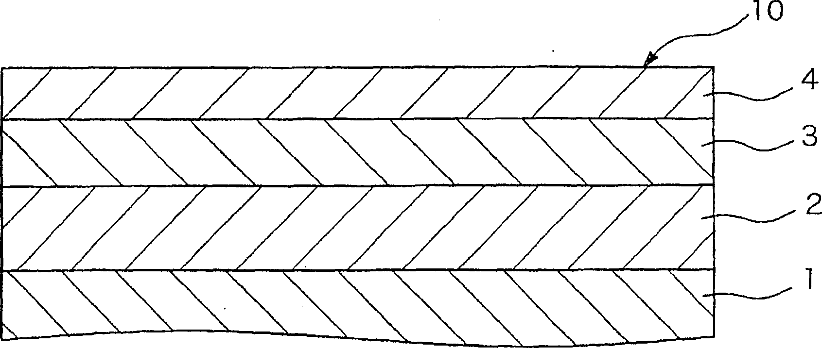
[0087] A non-magnetic substrate was prepared, which was a glass substrate for a 2.5-inch magnetic disk.
[0088] Place the non-magnetic substrate in a vacuum of 1×10 -5 The sputtering was performed by direct current magnetron sputtering in argon gas at 0.6 Pa pressure in a vacuum chamber heated to 250 °C.
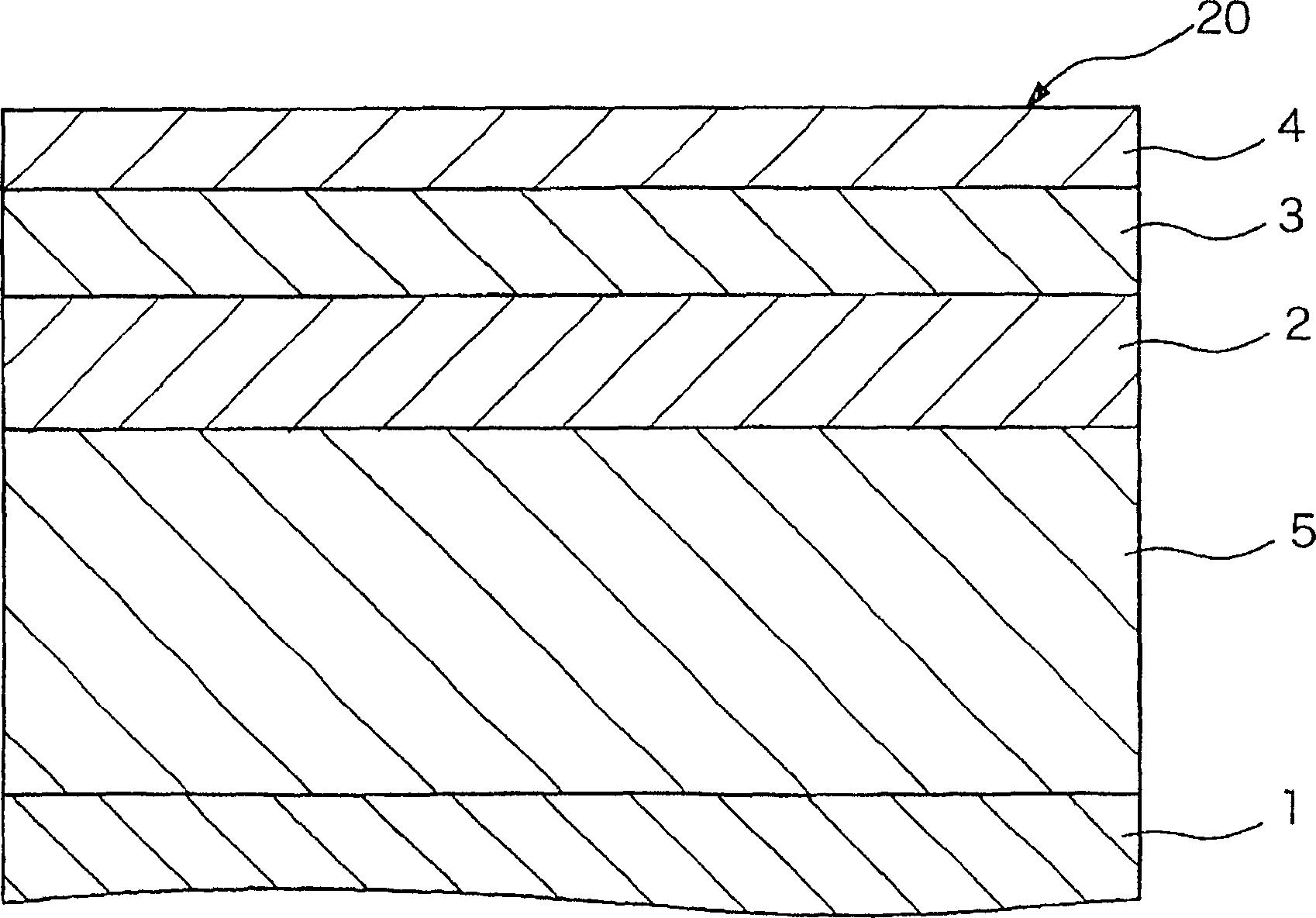
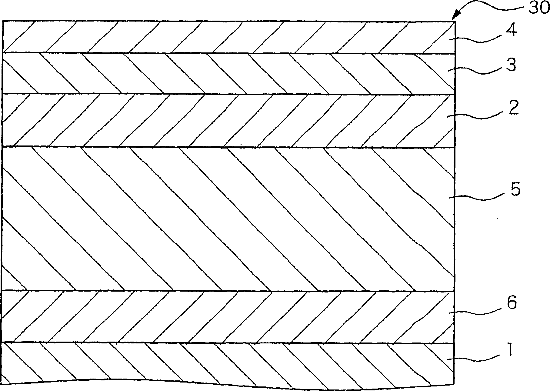
[0089] First, the non-magnetic substrate is set relative to the target, and electromagnetic radiation of 500 watts of direct current is radiated to the target to form a chromium layer with a thickness of 40 nanometers as a non-magnetic primer film. On this nonmagnetic undercoat film, a 25 nm thick CoCrPt ferromagnetic layer was formed as a bias application layer. A 200 nm thick CoZrNb soft magnetic layer was formed on the obtained CoCrPt ferromagnetic layer.
[0090] Thereafter, in a vacuum of 1×10 -5 Cool the substrate down to room temperature in a Pa vacuum chamber. A 10 nm-thick NiTa layer was formed on the CoZrNb soft magnetic layer as a nonmagnetic seed layer by us...
example 2
[0108]As the perpendicular magnetic recording layer of Example 2, a perpendicular magnetic recording medium was manufactured according to the same procedure as in Example 1, except that various oxides were used in the composite target, the target being Co-16at%Pt-10at% The composite target of Cr and CoPtCr-4mol% B (wherein A represents from Y 2 o 3 、WO 3 , MgO, Al 2 o 3 , ZrO 2 , HfO 2 At least one selected from, B stands for TiO 2 , CeO 2 , SiO 2 、Cr 2 o 3 , NiO, Ta 2 o 5 at least one selected from), which has oxide combinations of various elements shown in Table 1 below, instead of using CoPtCr-3mol%Y 2 o 3 -5mol% SiO 2 composite target.
[0109] In addition to the difference in the perpendicular recording layer, the obtained perpendicular magnetic recording medium has and Figure 5 The same layer structure is shown for the perpendicular magnetic recording medium.
[0110] The recording / reproducing characteristics of the obtained perpendicular magnetic recor...
example 3
[0114] As the perpendicular magnetic recording layer of Example 3, a perpendicular magnetic recording medium was manufactured according to the same method as Example 1, except that an oxide composite target having various composition ratios was used, and the target was CoPtCr-xmol%A -ymol% B composite target (where A represents from Y 2 o 3 and WO 3 At least one selected from, B stands for SiO 2 、Cr 2 o 3 and Ta 2 o 5 at least one selected from), which has various composition ratios shown in Table 2 below, instead of using CoPtCr-3mol%Y 2 o 3 -5mol% SiO 2 composite target.
[0115] In addition to the difference in the perpendicular recording layer, the obtained perpendicular magnetic recording medium has and Figure 5 The same layer structure is shown for the perpendicular magnetic recording medium.
[0116] The recording / reproduction characteristics of the obtained perpendicular magnetic recording medium of Example 3 were evaluated in a similar manner to Example 1....
PUM
| Property | Measurement | Unit |
|---|---|---|
| Size | aaaaa | aaaaa |
| Particle size | aaaaa | aaaaa |
| Particle size | aaaaa | aaaaa |
Abstract
Description
Claims
Application Information
 - R&D
- Intellectual Property
- Life Sciences
- Materials
- Tech Scout
- Unparalleled Data Quality
- Higher Quality Content
- 60% Fewer Hallucinations
Browse by: Latest US Patents, China's latest patents, Technical Efficacy Thesaurus, Application Domain, Technology Topic, Popular Technical Reports.
© 2025 PatSnap. All rights reserved.Legal|Privacy policy|Modern Slavery Act Transparency Statement|Sitemap|About US| Contact US: help@patsnap.com


