
Jet generator and electronic device

A technology for jetting generators and electronic equipment, applied in the direction of jetting devices, liquid jetting devices, instruments, etc., to achieve the effect of preventing vibration from being transmitted to the outside

Inactive Publication Date: 2006-11-08
SONY CORP
View PDF3 Cites 8 Cited by
  • Summary
  • Abstract
  • Description
  • Claims
  • Application Information

AI Technical Summary

Problems solved by technology

However, the increase in the number of revolutions of the fan to increase the air speed undesirably causes noise such as noise of the fan bearing and wind noise caused by the wind passing through the fan

Method used


Image

  • Jet generator and electronic device
  • Jet generator and electronic device
  • Jet generator and electronic device

Examples


Embodiment Construction

[0054] Embodiments of the present invention will now be described with reference to the accompanying drawings.

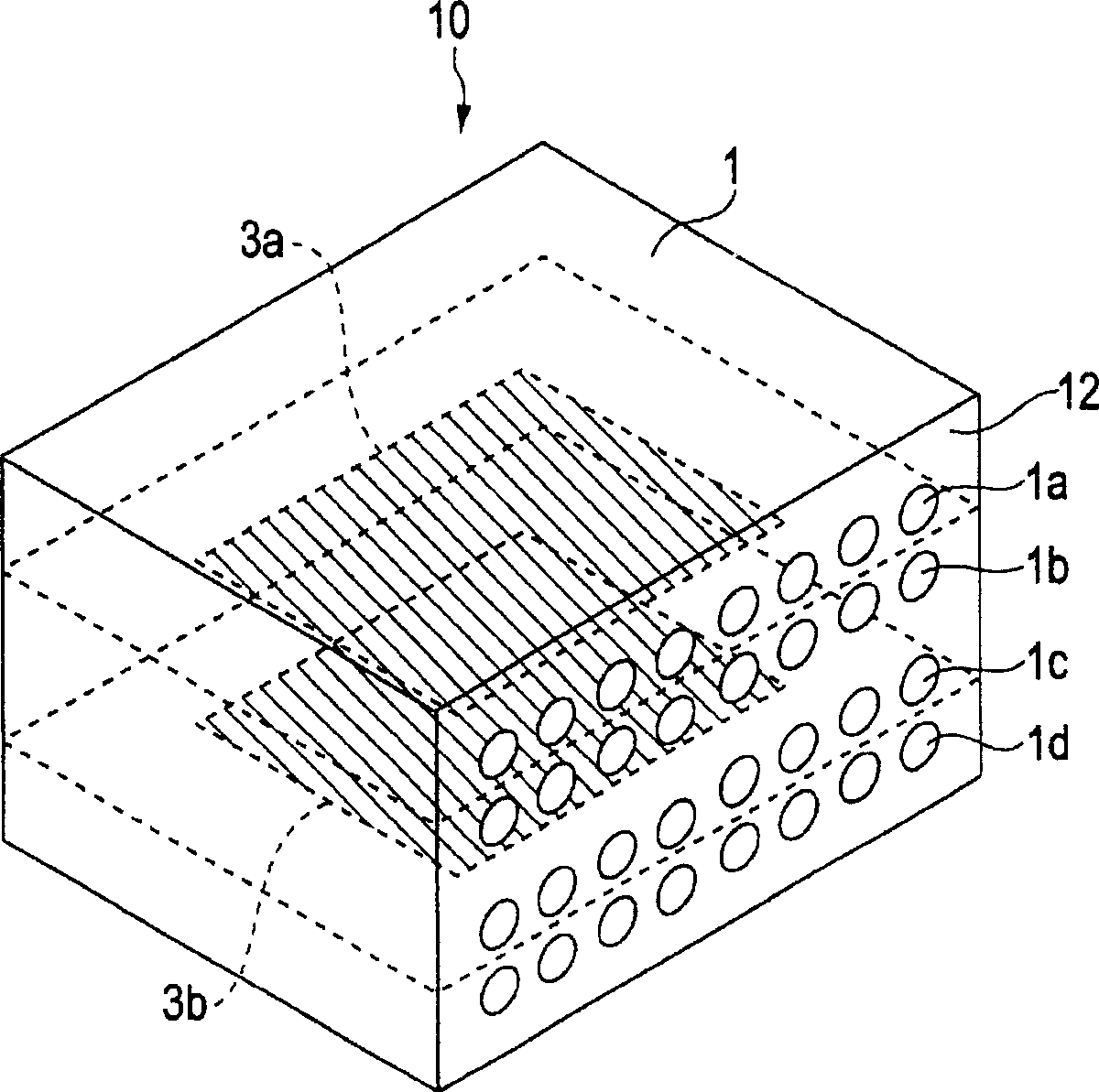
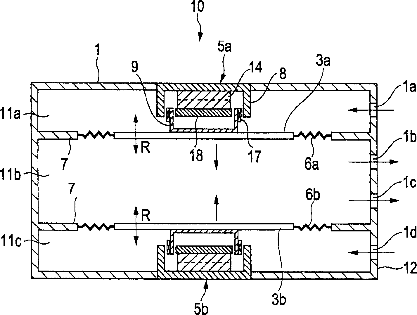
[0055] figure 1 is a perspective view of a jet generator in accordance with one embodiment of the present invention; figure 2 is a cross-sectional view of the jet generator.

[0056] The jet generator 10 comprises a housing 1 containing air. The housing 1 has, for example, a rectangular parallelepiped shape. The housing 1 includes, for example, two opposing membranes 3a and 3b and actuators 5a and 5b for driving the membranes 3a and 3b, respectively. For example, the actuator 5 a is provided on the top side of the housing 1 and the actuator 5 b is provided on the bottom side of the housing 1 . Elastic supports 6a and 6b are attached to the peripheries of the films 3a and 3b, respectively. The elastic supports 6 a and 6 b are also attached to ribs 7 protruding from the inner wall of the housing 1 . That is, the films 3 a and 3 b are attached to the elastic sup...


PUM


Abstract

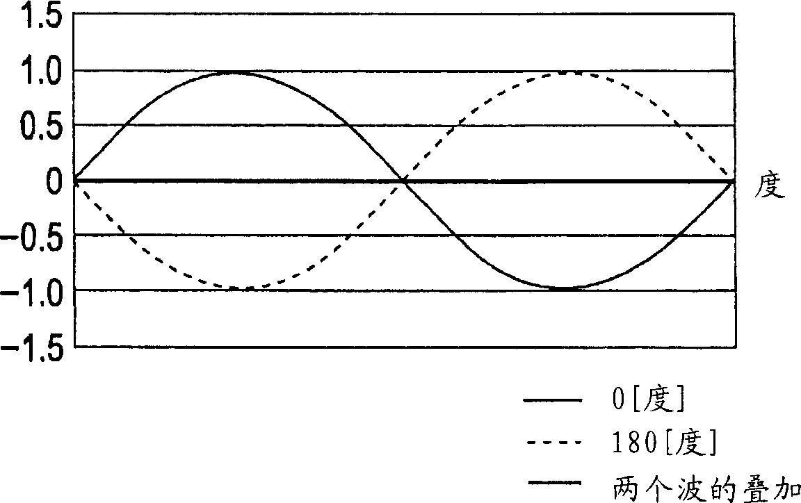
A jet generator includes a casing containing a gas and having an opening, vibrators attached to the casing, and actuators for actuating the vibrators. The vibrators vibrate with the vibrational forces thereof being synthesized so as to attenuate each other, thereby vibrating the gas to eject a pulsating jet thereof through the opening.

Description

technical field [0001] The invention relates to a jet generator for generating a gas jet and an electronic device comprising the jet generator. Background technique [0002] The increase in performance of personal computers (PCs) has caused the problem of an increase in heat generated by heat sources such as integrated circuits (ICs). Therefore, various heat dissipation methods have been proposed or commercialized. For example, a heat sink formed of a metal such as aluminum contacts the IC, transfers heat from the IC to the fin, and spreads it. In addition, a fan is used to forcibly discharge the hot air inside the PC case, and to introduce cold air from the outside to the vicinity of the heat source. Moreover, the combination of the fan and the heat sink forces the hot air around the heat sink to be exhausted, increasing the contact area between the air and the heat source. [0003] However, forced air convection by the fan forms a thermal boundary layer on the surface o...

Claims


Application Information

Patent Timeline
Patent Type & Authority Applications(China)
IPC IPC(8): B05B17/04G06F1/20H05K7/20
CPCG06F1/203G06F1/181G06F1/206H05K7/20136G06F2200/201
Inventor 横沟宽治石川博一牧野拓也中山典一武笠智治
Owner SONY CORP
Learn More