Rotor shaft controllable tilting coaxial rotor wing helicopter

A technology of rotor helicopters and rotor shafts, applied in the field of aircraft, can solve the problems of increased weight, limited weight of weights, small range of center of gravity changes, etc., and achieve high efficiency

Inactive Publication Date: 2006-11-08
胡俊峰
View PDF0 Cites 25 Cited by
  • Summary
  • Abstract
  • Description
  • Claims
  • Application Information

AI Technical Summary

Problems solved by technology

Compared with the Ka-1, the flying motorcycle can take off and land vertically, but due to the use of heavy blocks to adjust the center of gravity increases unnecessary weight, and the weight of the heavy blocks is limited, the range of change in the center of gravity is small

Method used


Image

  • Rotor shaft controllable tilting coaxial rotor wing helicopter
  • Rotor shaft controllable tilting coaxial rotor wing helicopter
  • Rotor shaft controllable tilting coaxial rotor wing helicopter

Examples


Embodiment 1

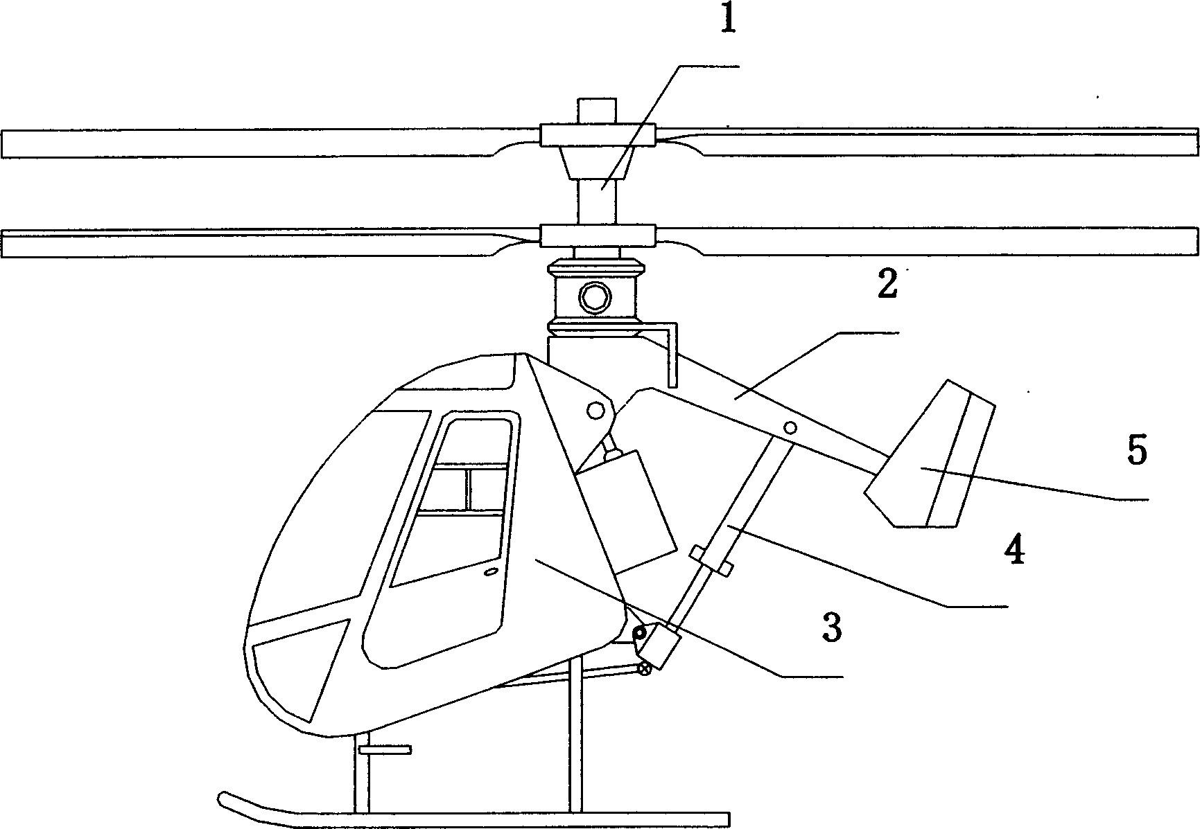
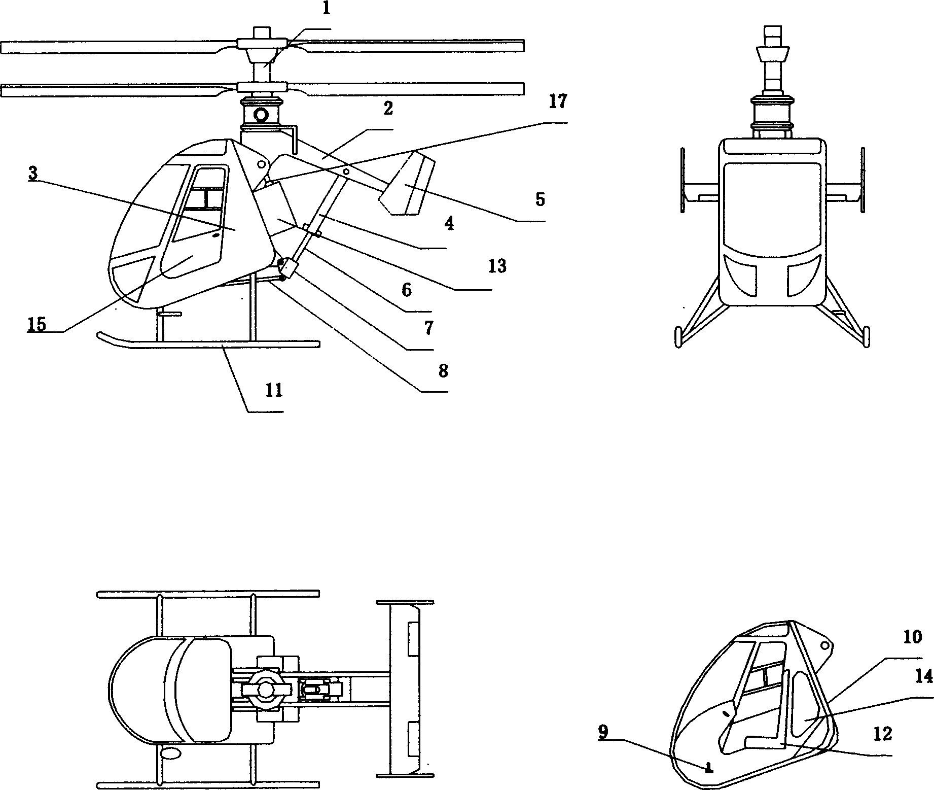
[0014] Embodiment 1 single-person helicopter: structure as attached image 3 As shown, the fuselage adopts a semi-monocoque structure. There are two side frames on the left and right, and the top is connected by two transverse reinforcement beams. The front part of the side frame is reinforced and fixed by two reinforcement beams and longitudinal beams. The part is fixedly connected with the backboard 10, and the skid landing gear 11 is fixedly connected with the backboard and the bottom of the side frame. The driver's seat 12 is placed in the cockpit, the bottom is fixed to the backboard, the engine 13 is fixed behind the backboard, and the fuel tank 14 is located between the seat and the engine, which is the position of the center of gravity of the whole machine during the standard load. Hatch door 15 is installed on the left side side frame with hinge.

[0015] as attached Figure 4 As shown, the tail boom is composed of two beams, the front part has a hinge matching the ...

Embodiment 2

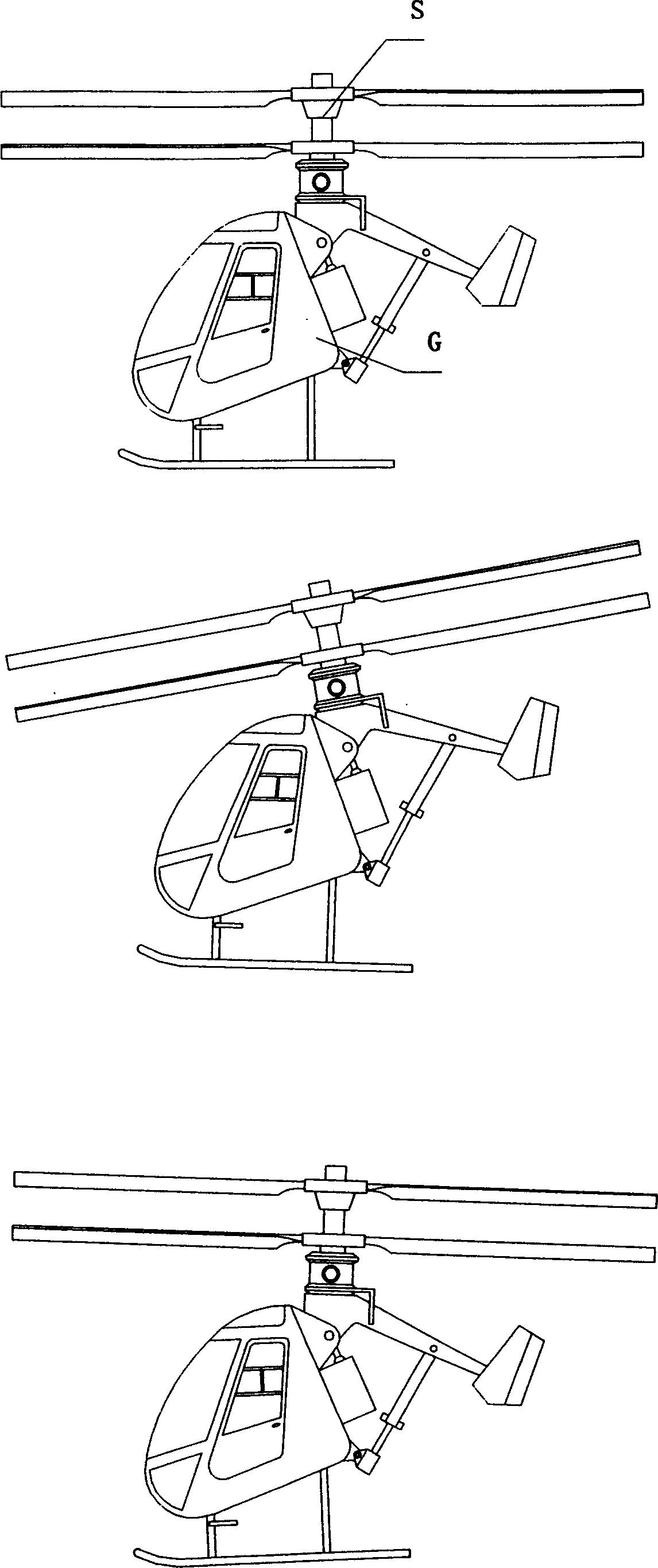
[0020] Embodiment 2 unmanned helicopter: structure such as Image 6 As shown, the engine transmission is installed on the tail boom, and the transmission drives the helical gear in the axle box through a pair of pulleys to drive the rotor to rotate. The top of the tail beam is hinged to the fuselage, the hydraulic cylinder is hinged to the bottom of the tail beam, and the top of the piston rod is hinged to the bottom of the fuselage. There are short wings on both sides of the tail boom to generate lift, and the rear is a tail connected by struts. Inside the fuselage are the load space, the flight control system and the fuel tank.


PUM


Abstract

The coaxial rotor wing helicopter with controllable inclined rotor shaft has fixed rotor elevation, rotor shaft fixed before the tailboom, hinge device connecting tailboom to the fuselage and flight attitude regulator of adjustable length connecting the tailboom to the fuselage. Regulating the length of the flight attitude regulator can regulate the position of the rotor shaft extension line relatively to the helicopter gravity center, and when the rotor shaft extension line coincides with the gravity center, the helicopter is in vertical lift state. Increasing the length of the flight attitude regulator to make the gravity center in front of the rotor shaft extension line makes the helicopter fly forwards; and decreasing the length of the flight attitude regulator to make the gravity center in back of the rotor shaft extension line makes the helicopter fly backwards. The engine throttle controls the rotation speed of the rotor wing, while vertical tail wing regulates the flying direction.

Description

technical field [0001] The invention relates to an aircraft, in particular to a coaxial rotor helicopter Background technique [0002] Kamov designed a large number of coaxial rotor helicopters. Unlike the large helicopters controlled by swash plates, the original design of the Ka-1 single-person helicopter rotor is very simple, and the elevation angle is fixed on the rotor shaft. In this way, it generates lift The size of the rotor is completely determined by the rotation speed of the rotor. The rotor shaft is fixedly installed in the middle of the fuselage, driven by the engine at the rear, and the driver is located at the front. The last pair of vertical tails is controlled by the joystick, and a pair of airbags are used as landing gear. . When there is a driver, the center of gravity is located in front of the rotor shaft, so that the helicopter can only fly forward, and the deflection of the tail will make the helicopter turn left and right. The flight color height is ...

Claims


Application Information

Patent Timeline
Patent Type & Authority Applications(China)
IPC IPC(8): B64C27/00
Inventor 胡俊峰
Owner 胡俊峰
Why Eureka
Try Eureka