Structure of gas-liquid separator with rotary dual cylinder compressor

A gas-liquid separator and compressor technology, which is applied in the field of compressors, can solve the problems of high cost, difficult installation, and easy resonance, etc., and achieve the effect of reducing the number or volume, easy installation and production, and saving pipe costs

Inactive Publication Date: 2006-11-15
LG ELECTRONICS (TIANJIN) APPLIANCES CO LTD
View PDF1 Cites 2 Cited by
  • Summary
  • Abstract
  • Description
  • Claims
  • Application Information

AI Technical Summary

Problems solved by technology

[0011] However, in the gas-liquid separator of the conventional rotary double-pressure cylinder compressor as described above, the suction pipes 13A, 13B in the shroud 11 are arranged side by side in the gas-liquid separator, so that the volume becomes large, which wastes material and It is not easy to install, and it is easy to cause resonance, increase the noise of the compressor, and have a bad influence on the compressor
[0012] In order to solve the above problems, the suction pipe structure of the gas-liquid separator of the rotary double-pressure cylinder compressor disclosed in Chinese Patent Application No. 200410093783.9, the suction pipe is redesigned into the main suction pipe and the two-part suction pipe and connected into an inverted Y shape, which reduces the compression pressure. The noise of the gas-liquid separator of the machine, but there are still problems in the connection and assembly of the primary and secondary suction pipes in the gas-liquid separator, which are complicated, costly, and bulky

Method used


Image

  • Structure of gas-liquid separator with rotary dual cylinder compressor
  • Structure of gas-liquid separator with rotary dual cylinder compressor
  • Structure of gas-liquid separator with rotary dual cylinder compressor

Examples


Embodiment Construction

[0039] In order to further understand the invention content, characteristics and working process of the present invention, give examples of the following embodiments, and cooperate with the accompanying drawings to describe in detail as follows:

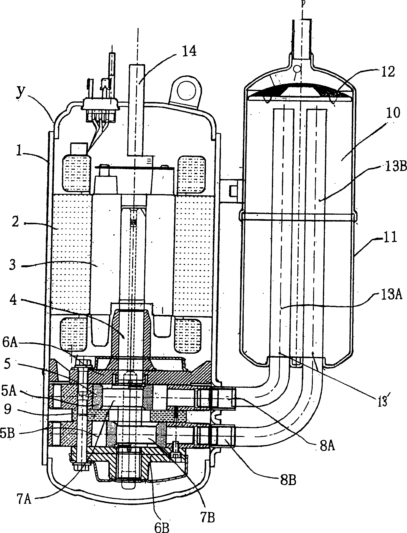
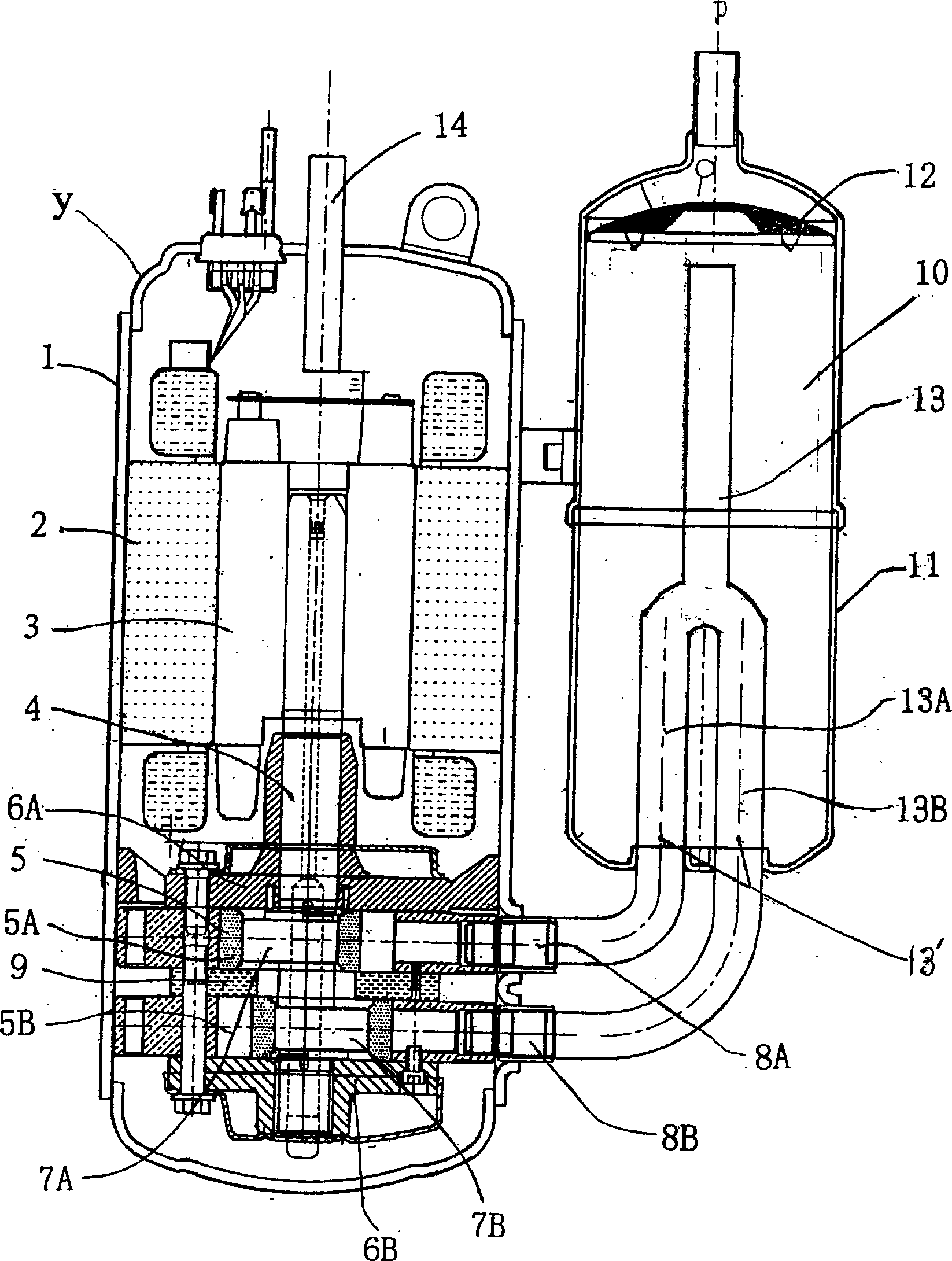
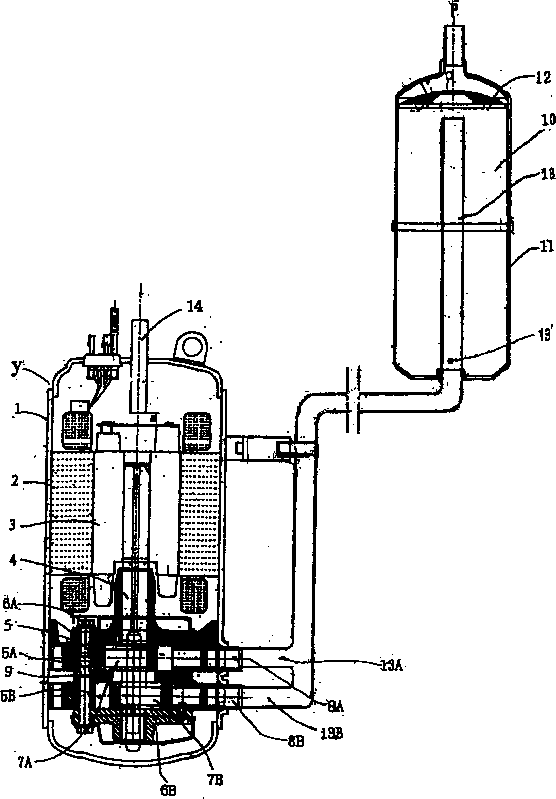
[0040] image 3 It is a structural diagram of the double-cylinder suction pipe of the separator of the present invention. The same symbols are used for the same parts as the previous technology

[0041] As shown in the figure, the rotary double-cylinder compressor according to the present invention consists of a casing 1; a stator 2 and a rotor 3 of the electric structural part are arranged inside the casing, wherein the center of the rotor 3 is pressed into the rotating shaft 4, and the center of the rotating shaft 4 The lower part is composed of a compression structure for sucking and compressing refrigerant gas.

[0042] The compression structure part includes a cylinder 5 fixed on the lower peripheral surface of the casing 1. T...


PUM


Abstract

The invention consists of a protection cover forming a gas-liquid separator casing, an air intake pipe in communication with the exhaust pipe of an evaporator disposed on the top of the protection cover, a filter screen for separating gas and liquid refrigerants disposed in the upper part of the protection cover and a suction pipe. The suction pipe is made up of a main suction pipe whose one end going deep into the upper part of the protection cover and the other end connected with two branch suction pipes outside the protection cover and two branch suction pipes inserted into the upper and lower suction ports of the cylinder.

Description

technical field [0001] The invention belongs to the technical field of compressors, and in particular relates to changing the design of the double-cylinder suction pipe of the gas-liquid separator to simplify the manufacture of the gas-axle separator, and the structure of the gas-liquid separator of the rotary double-cylinder compressor that can be arranged and installed separately to reduce the volume of the air conditioner . Background technique [0002] Rotary compressors generally used in air conditioners are rotary pistons that are eccentrically combined with a compression mechanism on a rotating shaft combined with an electric mechanism. The rotary piston rotates in the compression space of a circular cylinder to suck, compress, and discharge refrigerant. . [0003] If the rotary compressor sucks the refrigerant directly from the evaporator, there is a danger that the gas refrigerant and the liquid refrigerant will flow together. Therefore, a gas-liquid separator devi...

Claims


Application Information

Patent Timeline
Patent Type & Authority Applications(China)
IPC IPC(8): F04C29/00F04C18/344F04C23/00
Inventor 娄新颜
Owner LG ELECTRONICS (TIANJIN) APPLIANCES CO LTD
Why Eureka
Try Eureka