Power assembly experimental apparatus for hybrid power automobile

A technology of hybrid electric vehicles and powertrains, which is applied in the field of automobile experiments and can solve problems such as inability to test

Inactive Publication Date: 2006-11-22
CHERY AUTOMOBILE CO LTD
View PDF0 Cites 23 Cited by
  • Summary
  • Abstract
  • Description
  • Claims
  • Application Information

AI Technical Summary

Problems solved by technology

The traditional car has only one power source, and there is no problem of power distribution. The experimental device is designed for the engine and is a mechanical drive route.
Traditional testing schemes cannot test for this
At the same time, in the

Method used


Image

  • Power assembly experimental apparatus for hybrid power automobile

Examples


Example Embodiment

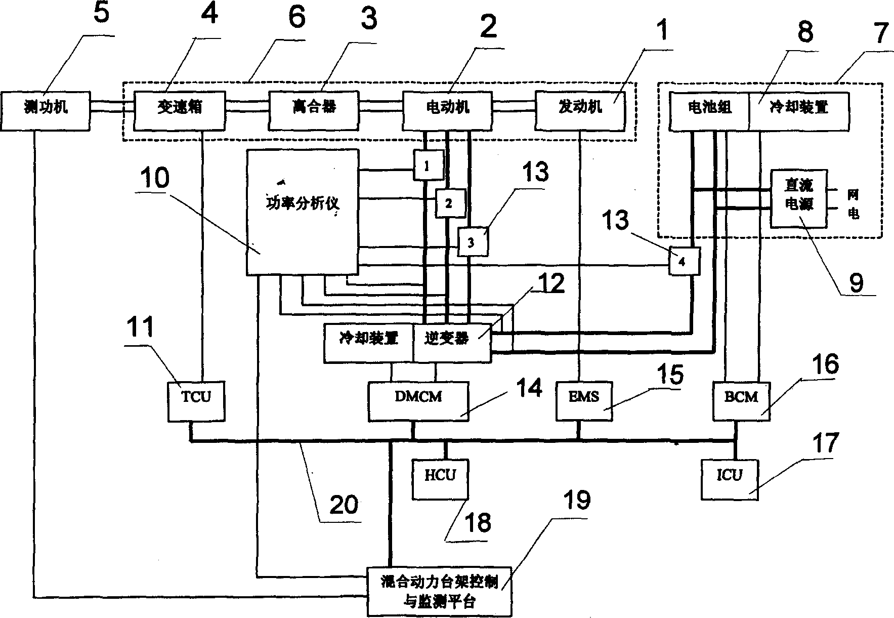
[0013] Such as figure 1 As shown, a hybrid electric vehicle powertrain test device includes an engine 1, a clutch 3, a gearbox 4 connected to a dynamometer 5, an engine controller 15, and a gearbox controller 11, which are located in the powertrain 6. There is an electric motor 2 coaxially connected with the engine 1 and the clutch 4 respectively. The engine 1, the electric motor 2, the clutch 3 and the gearbox 4 are assembled and connected in sequence to form a hybrid power assembly 6.

[0014] The output of the power supply 7 is connected to the motor 2 through the inverter 12, and the DC power is inverted into three-phase AC power through the inverter 12 to supply power to the motor 2. The inverter 12 is provided with a cooling device. The power supply 7 is composed of a battery pack 8 and a DC power supply 9 connected in parallel at the output end. The battery pack 8 is provided with a cooling device. The DC power supply 9 charges the battery pack 8 or supplies power to the in...


PUM


Abstract

The disclosed experiment device for mixed-power vehicle power assembly comprises: a motor connected to the engine and clutch and the power supply through an inerter, a power analyzer connected to the detector, the supply and the sensor in motor loop to analyze collected different currents and record working state precisely; a cell management unit, a motor controller, and other controllers for motor, gear-box, and multi-energy, and a meter unit all connected to the detector by CAN bus.

Description

technical field [0001] The invention relates to automobile experiment technology, in particular to a hybrid electric vehicle powertrain experiment device Background technique [0002] Since a hybrid vehicle includes two power sources of an engine and an electric motor, multiple controllers such as an engine management unit, a multi-energy control unit, a motor controller, and a battery management unit have complex operating modes, which are very different from traditional vehicles. Therefore, it is necessary to test its various components, verify and debug its various functions. The traditional car has only one power source, and there is no power distribution problem. The experimental device is designed for the engine and is a mechanical drive route. Traditional testing scenarios cannot test for this. At the same time, in the acceleration, deceleration, starting and other working conditions of the hybrid vehicle, it involves the torque distribution of the engine and the mo...

Claims


Application Information

Patent Timeline
IPC IPC(8): G01M17/007
Inventor 方运舟刘攀林伟程丰林
Owner CHERY AUTOMOBILE CO LTD
Why Eureka
Try Eureka