

Autofocus control method, autofocus controller, and image processor
A technology of automatic focusing and control method, applied in the direction of instrument, installation, optics, etc., can solve the problem of not being able to find the focus position stably, and achieve the effect of high-resolution observation
- Summary
- Abstract
- Description
- Claims
- Application Information
AI Technical Summary
Problems solved by technology
Method used
Image

Examples
no. 1 example
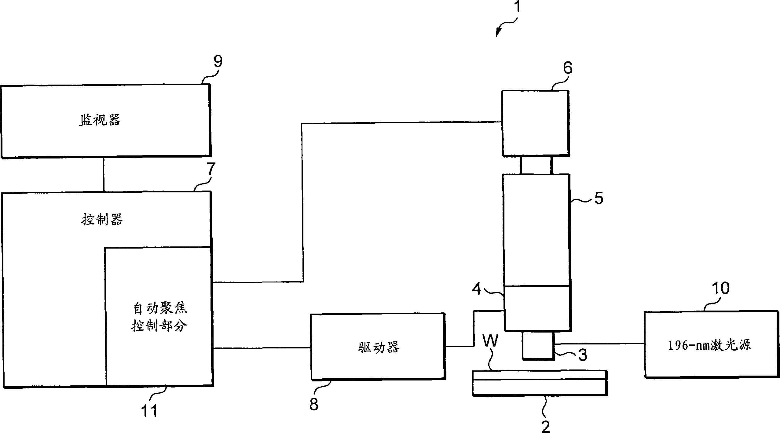
[0042] figure 1 is a schematic structural diagram of an image processing device, on which the automatic focus control method and the automatic focus control device according to the embodiments of the present invention are adopted. Surface observation of an object sample (work) is performed with an image processing apparatus 1 specially constructed as a microscope for defect inspection of a device structure such as a semiconductor wafer by made by micromachining.
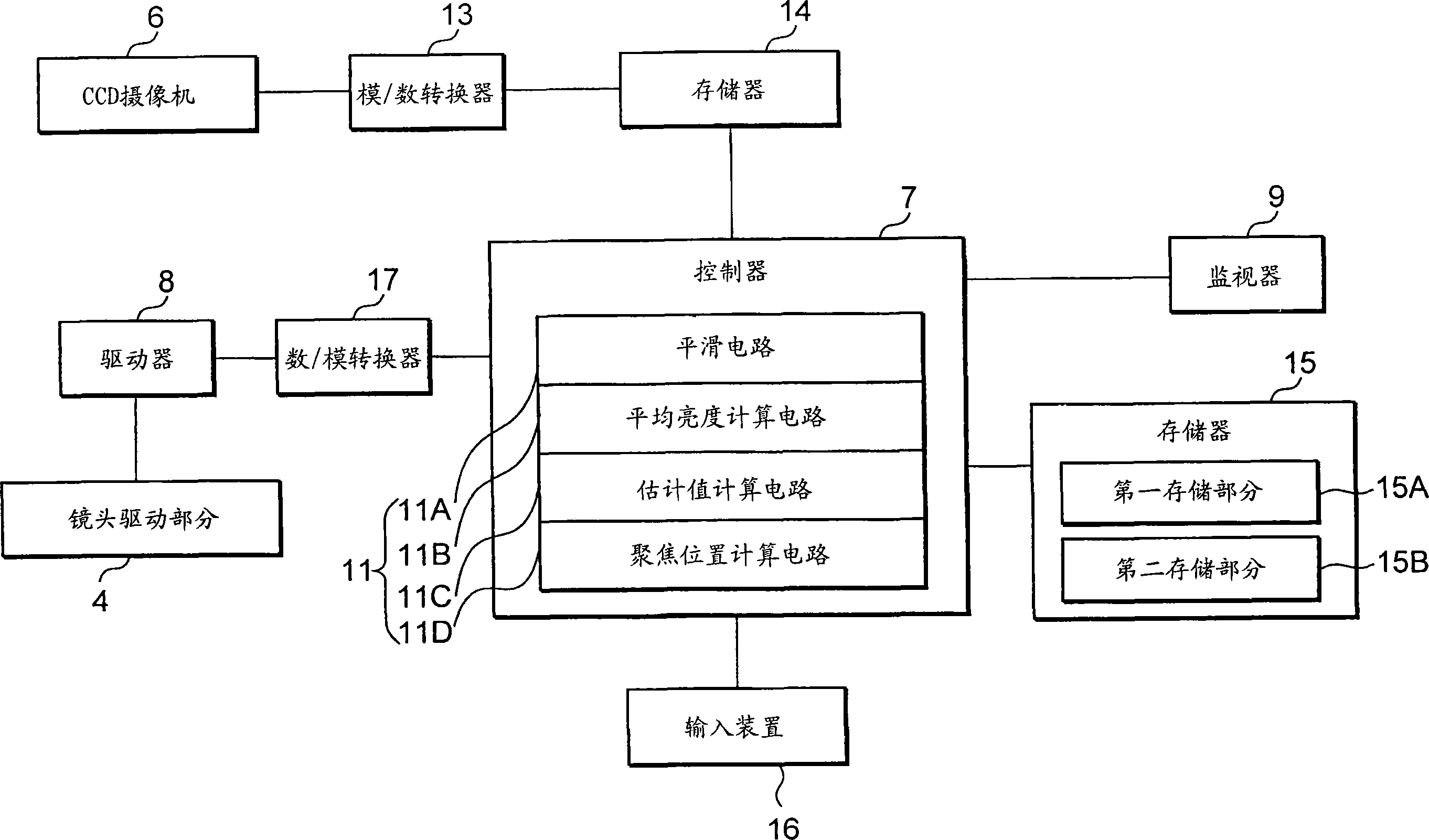
[0043] The image processing device 1 is equipped with a measurement platform 2 , an objective lens 3 , a lens driving part 4 , a lens barrel 5 , a CCD (charge coupled device) camera 6 , a controller 7 , a driver 8 , a monitor 9 and an illumination source 10 .
[0044] The measuring table 2 is constructed to support an object sample (for example, a semiconductor wafer) W and in the X-Y direction (in figure 1 , in the left-right direction and in the direction perpendicular to the drawing page).
[0045] Within the...
no. 2 example
[0107] Next, a second embodiment of the present invention will be described.
[0108] When miniaturization (processing rule) of the minimum mode width is performed, recent semiconductor wafers start to adopt more three-dimensional structures in their height direction. Light sources with shorter wavelengths require shallower depths of focus and are not conducive to reducing the number of focusable portions of objects with large height differences. If there are height differences in the screen, and different surfaces can be focused at different heights, an effective focusing operation must be performed to determine "where to focus", i.e. which surface of the sample to use as a reference surface. However, the conventional autofocus control method of finding the optimum focus position based on the focus estimation value has a disadvantage in that it cannot focus on a desired portion.
[0109] In order to solve this problem, a method will be described below which employs the auto...
no. 3 example
[0120] Next, a third embodiment of the present invention will be described. In describing this embodiment, a method of synthesizing a full-focus image of a subject sample based on the obtained image data and using the autofocus control method according to the present invention was cited.
[0121] In the case of a normal optical system, if a three-dimensional object beyond the focal depth of the optical system is observed through it, the overall focused image cannot be seen, and therefore, the purpose of inspection or observation cannot be achieved. Try to solve this problem with the following two methods, one of which is to use a special optical system such as a confocal optical system to obtain an overall focused full-focus image, and the other is to obtain an overall focus from images from different angles according to trigonometry A focused image, however, cannot be achieved cheaply by either of the above methods due to the need to use special optical systems.
[0122] On ...
PUM
 Abstract
Description
Claims
Application Information