
Automatic control method for central cold supply system

An automatic control, central cooling technology, applied in heating and ventilation control systems, heating and ventilation safety systems, household heating, etc. Clear goals, energy-saving operating costs, and the effect of reducing operating costs

Active Publication Date: 2006-11-29
GUANGZHOU METRO GRP CO LTD +1
View PDF0 Cites 24 Cited by
  • Summary
  • Abstract
  • Description
  • Claims
  • Application Information

AI Technical Summary

Problems solved by technology

[0003] 1. Each centralized cooling station needs to control multiple sets of intelligent equipment such as chillers and variable frequency pumps, and multiple sets of terminal combined air conditioners. There are many process variables that require regulation. It belongs to a multivariable regulation system. There are many related factors and it is impossible to accurately establish a control model.
[0004] 2. The transmission distance of chilled water is long, and the system time is prolonged, so it is difficult to realize real-time control
[0005] 3. During the control process, the flow rate of the primary pump should match the operating efficiency of the chiller as much as possible, and the flow rate of the secondary pump should track the demand of the end combination air conditioner in real time, and the flow rate of multiple end combination air conditioners also exists during the adjustment process. Interference with each other makes flow adjustment equipment such as frequency conversion pumps and control valves must take into account the adjustment and matching of multiple flows. According to conventional control, it will often jump back and forth between the minimum value and the maximum value. The system is very unstable and easy to oscillate.
[0006] 4. Due to the influence of factors such as seasons, outdoor ambient temperature, and changes in the flow of people at the terminal, the demand for chilled water flow of the combined air conditioner at the terminal will vary greatly. Load demand changes, resulting in waste of energy consumption and increased operating costs

Method used


Image

  • Automatic control method for central cold supply system
  • Automatic control method for central cold supply system
  • Automatic control method for central cold supply system

Examples


Embodiment Construction

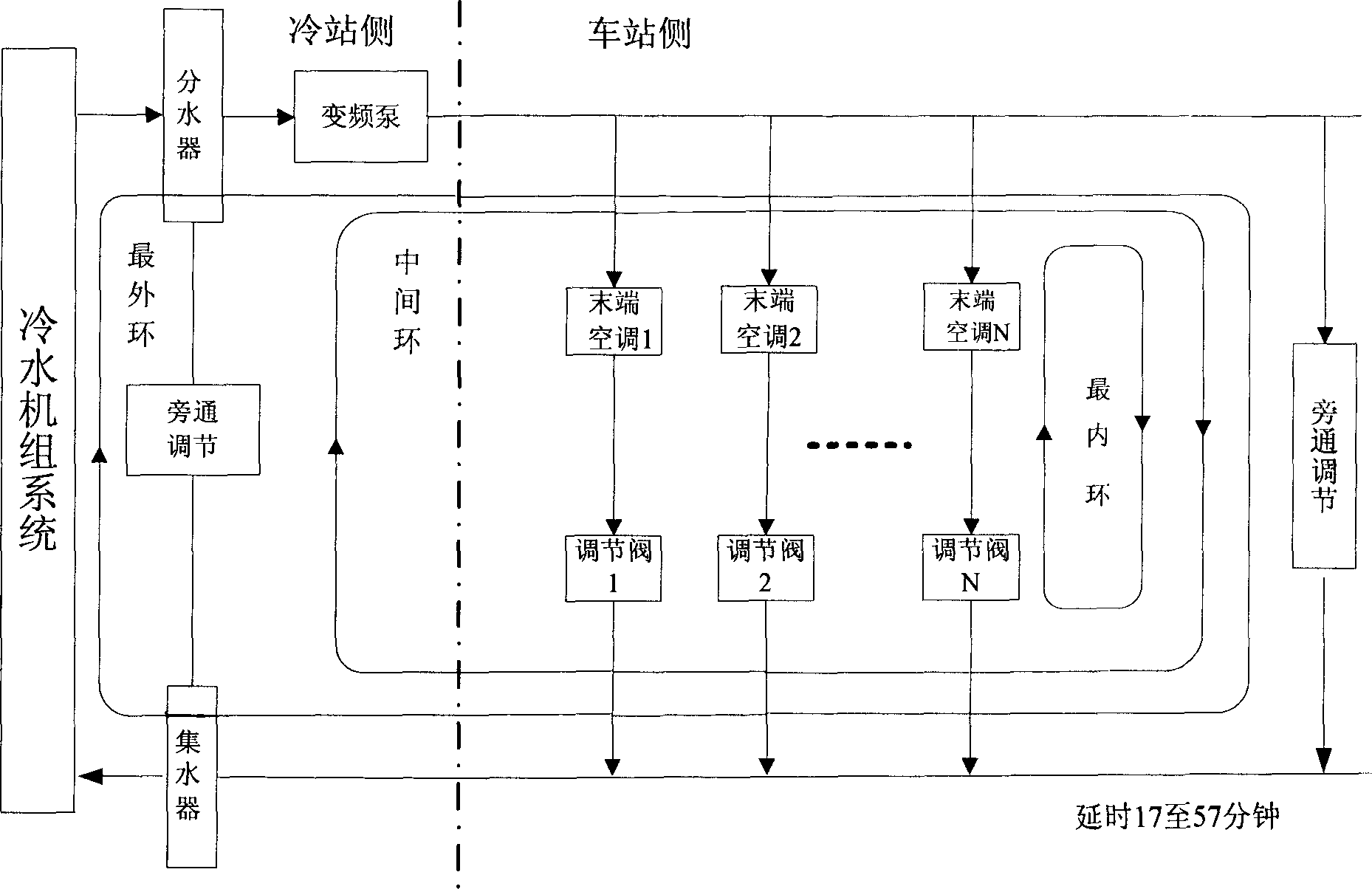
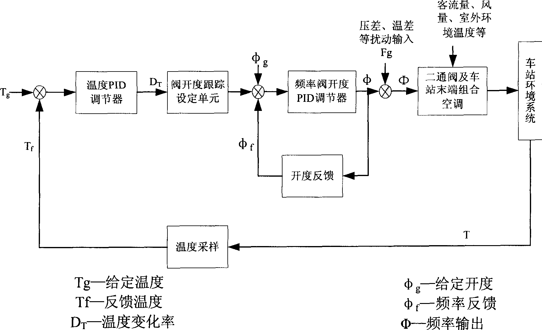
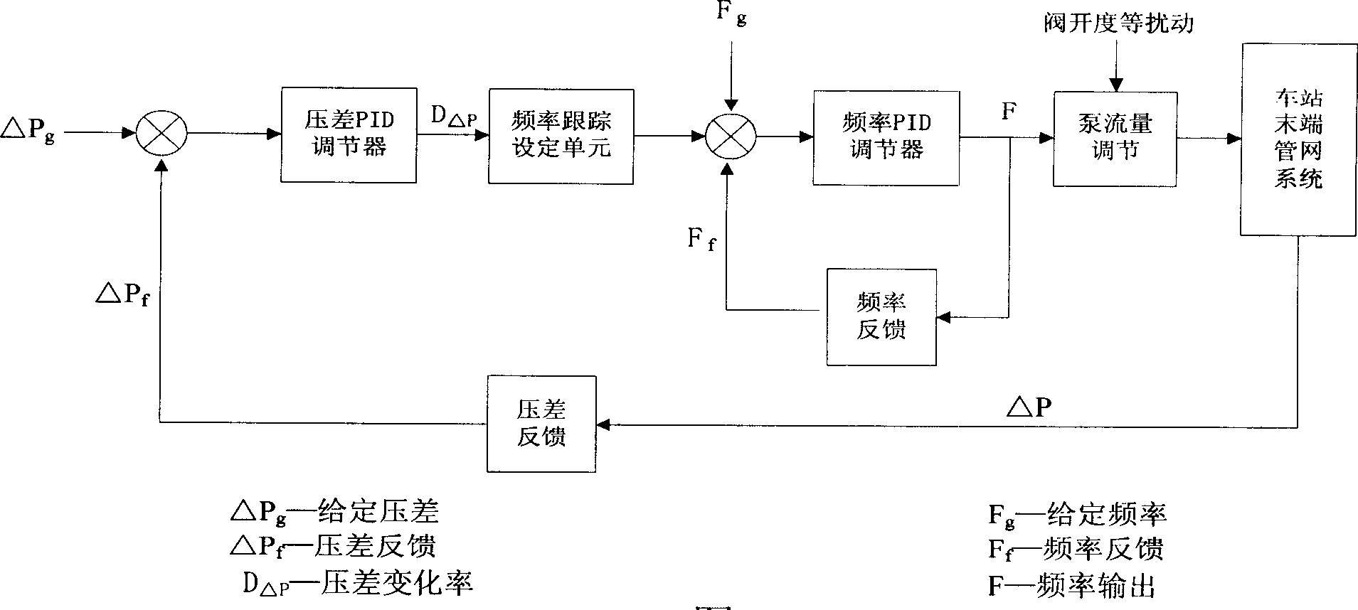
[0034] Such as figure 1 As shown, the air-conditioning water supply system of the entire cold station is decomposed into a three-loop regulation system. According to the idea of ​​principal component analysis, many control objects and process control parameters in the system are decomposed and considered, so that the chiller group control, frequency conversion The pump control and regulating valve control are relatively independent and interdependent, and the control objectives are clear. The specific description is as follows:

[0035] 1. Decoupling of control objects and control variables

[0036] 1) Take the control of the terminal air conditioner and its control valve as the inner loop, take the ambient temperature as the control variable, the opening of the control valve as the adjustment variable, and others such as: chilled water temperature, station passenger flow, chilled water pressure difference, etc. as disturbance variables ;

[0037] 2) The control of the vari...


PUM


Abstract

The invention discloses an automatic control method of centralized cold providing system. It is a recurrent cold providing system which includes cooling water set, a frequency conversion pump, freezing water pipes net and the terminal air-condition units. The control method is that the recurrent cold proving system is disassembled many unattached control circle. A main control parameter and a regulable parameter are set in each circle. Through adjusting the parameters to adjust and control the change of the parameter, in different circles the control parameters and the regulable parameter interfere each other. The automatic control method provides a systemic solution for centralized cold providing system. It can comparatively separate the control of key equipments, such as the cold water motors, the frequency conversion pump, the adjusting valve etc. It deals with the influence of each other as a interferential variable to definitize the control target, run stably. So it can realize economizing energy and depressing the running cost.

Description

technical field [0001] The invention relates to the field of automatic control of a central cooling system, in particular to an automatic control method of a centralized cooling system, including a frequency conversion adjustment method of a frequency conversion pump, a control valve opening adjustment method and a group control method of chillers. Background technique [0002] The centralized cooling system is to centralize the cooling at the centralized cooling station, and then send the centralized cooling load to each end in real time through the pump and chilled water pipe network, so as to realize the automatic control of the ambient temperature of the remote large area and large space. Its control difficulties mainly include: [0003] 1. Each centralized cooling station needs to control multiple sets of intelligent equipment such as chillers and variable frequency pumps, and multiple sets of terminal combined air conditioners. There are many process variables that req...

Claims


Application Information

Patent Timeline
Patent Type & Authority Applications(China)
IPC IPC(8): F24F11/00
Inventor 陈韶章贺利工陈迪泉俞军燕耿望阳高俊霞陈建荣韩瑶
Owner GUANGZHOU METRO GRP CO LTD
Learn More