System and method of chamber destruction of bomb

A technology of chambers and bombs, which is applied in the field of bomb destruction systems in chambers, can solve the problems of high security intensity, workload of warning, and difficulty in finding bomb sites, so as to prevent flying out of the chamber, resist long-term weathering, and ensure safety. improved effect

Inactive Publication Date: 2006-11-29
GUANGDONG HONGDA BLASTING
View PDF0 Cites 7 Cited by
  • Summary
  • Abstract
  • Description
  • Claims
  • Application Information

AI Technical Summary

Problems solved by technology

[0002] In the prior art, the method of digging trenches and burying the bombs is generally used to destroy the bombs. The disadvantage is that it requires a large space range and the security intensity is very high, resulting in a very large amount of security work and a large number of police forces when destroying weapons. Only by maintaining order can bombs be destroyed safely, especially in densely populated areas, where the workload and difficulty of evacuating personnel is quite large, which brings a great burden to the security work
In modern society, with the rapid development of science and technology and the rapid expansion of cities to surrounding areas, it is becoming more and more difficult to find sites for bomb destruction. Therefore, the existing technology can no longer meet the requirements of the times

Method used


Image

  • System and method of chamber destruction of bomb
  • System and method of chamber destruction of bomb
  • System and method of chamber destruction of bomb

Examples


Embodiment 1

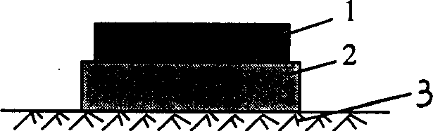
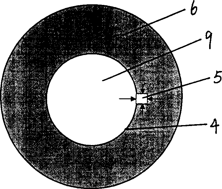
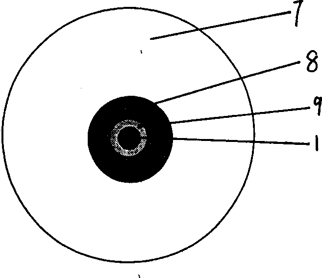
[0033] Figure 1-4 The shown chamber destruction bomb system is an embodiment of the present invention, consisting of a destruction chamber 9, two adit 11 and two connection lanes 10, and the destruction chamber 10 is located in the surrounding rock 6 The underground space in the middle, it is located between the two arks 11 and on the same side as the two adits 11, and is connected with the adit 11 through the connection alley 10; Adopt naked alleyways. The destruction chamber 9 is set in hard granite with a compressive strength of 150Mpa, making it suitable for destroying bombs with an explosive equivalent of 200kg or less; the distance from the destruction chamber 9 to the ground surface is 16m, and its volume is 85m 3 , with a span of 7.0m; the bottom plate 3 of the destruction chamber 9 is covered with a sand cushion 2 with a height of 1m, and the bomb and the detonating charge package 1 are placed on it; the roadway formed by each of the connecting lanes 10 and 11 has ...

Embodiment 2

[0037] Such as Figure 5 Shown chamber destruction bomb system is the second embodiment of the present invention, and it is different from Embodiment 1 by destroying chamber 9, a pit 11 and a connection lane 10, and destroying chamber 9 and pit 11 is on the same side. The distance from the said destruction chamber 9 to the surface is 15m, and its volume is 90m 3 , span 8.0m; the bottom plate 3 of the destruction chamber 9 is covered with a sand cushion 2 with a height of 1.5m, the length of the connecting lane 10 is 10m, the length of the adit 11 is 30m, and the space in the aisle and the lane is 190m 3 , set up an explosion-proof retaining wall 12 at a distance of 3m from the entrance of the chamber.

Embodiment 3

[0039] Such as Image 6 Shown chamber destruction bomb system is the third embodiment of the present invention, and it is different from Embodiment 1 and is made of destruction chamber 9, a pit 11 and a connection lane 10, and destruction chamber 9 is positioned at flat Cave 11 is on the opposite side. The distance from the said destruction chamber 9 to the surface is 20m, and its volume is 100m 3 , span 10m; the bottom plate 3 of the destruction chamber 9 is covered with a sand cushion 2 with a height of 2m, the length of the connecting road 10 is 35m, the length of the avenue 11 is 40m, and the space in the cave and the road is 200m 3 , Set up an explosion-proof retaining wall 12 at a distance of 4m from the entrance of the chamber.


PUM


Abstract

The invention discloses a system and method to destroy bomb in underground chamber that is made up of destroying underground chamber located in wall rock and the bottom has impacting resistance material layer, adit and communicating laneway that has laneway structure. The destroying underground chamber connects to adit through laneway. After setting the system, laying the bomb and blasting charge into the underground chamber to take remote detonation and take forced draught after detonating to release the waste gas into atmosphere and the harmful gas thickness would be lowered to safe range. The system would destroy 200kg detonator equivalent weight bomb, and the bow wave would not harm human over 200m distance. Even in the area of popuousness.

Description

technical field [0001] The invention relates to a system and method for destroying bombs, in particular to a system and method for destroying bombs in a chamber. Background technique [0002] In the prior art, the bomb is generally destroyed by digging trenches on the ground and burying it. The disadvantage is that it requires a large space range and the security intensity is very high, resulting in a very large amount of security work and a large number of police forces when destroying weapons. Only by maintaining order can bombs be destroyed safely. Especially in densely populated areas, the workload and difficulty of evacuating personnel are quite large, which brings a great burden to the security work. In modern society, with the rapid development of science and technology and the rapid expansion of cities to surrounding areas, it is becoming more and more difficult to find sites for bomb destruction. Therefore, the existing technology can no longer meet the requirements...

Claims


Application Information

Patent Timeline
Patent Type & Authority Applications(China)
IPC IPC(8): F42D5/04E21D9/14
CPCF42D5/045
Inventor 郑炳旭张小穗王念省傅建秋徐杰彭金祥王永庆林再坚
Owner GUANGDONG HONGDA BLASTING
Why Eureka
Try Eureka