
Gear change mechanism, and speed changing method of motor vehicles

A transmission device and motor vehicle technology, applied in control devices, vehicle parts, transportation and packaging, etc., can solve problems such as power interruption, vehicle power performance impact, etc., to achieve the effect of reducing power loss and improving power performance

Active Publication Date: 2006-12-06
BYD CO LTD
View PDF0 Cites 3 Cited by
  • Summary
  • Abstract
  • Description
  • Claims
  • Application Information

AI Technical Summary

Problems solved by technology

In this way, there will be a problem: in the process of shifting gears, the vehicle is not driven by power, which will cause power interruption during driving and affect the dynamic performance of the vehicle.

Method used


Image

  • Gear change mechanism, and speed changing method of motor vehicles
  • Gear change mechanism, and speed changing method of motor vehicles
  • Gear change mechanism, and speed changing method of motor vehicles

Examples


Embodiment Construction

[0029] Specific embodiments of the present invention will be described in detail below with reference to the accompanying drawings.

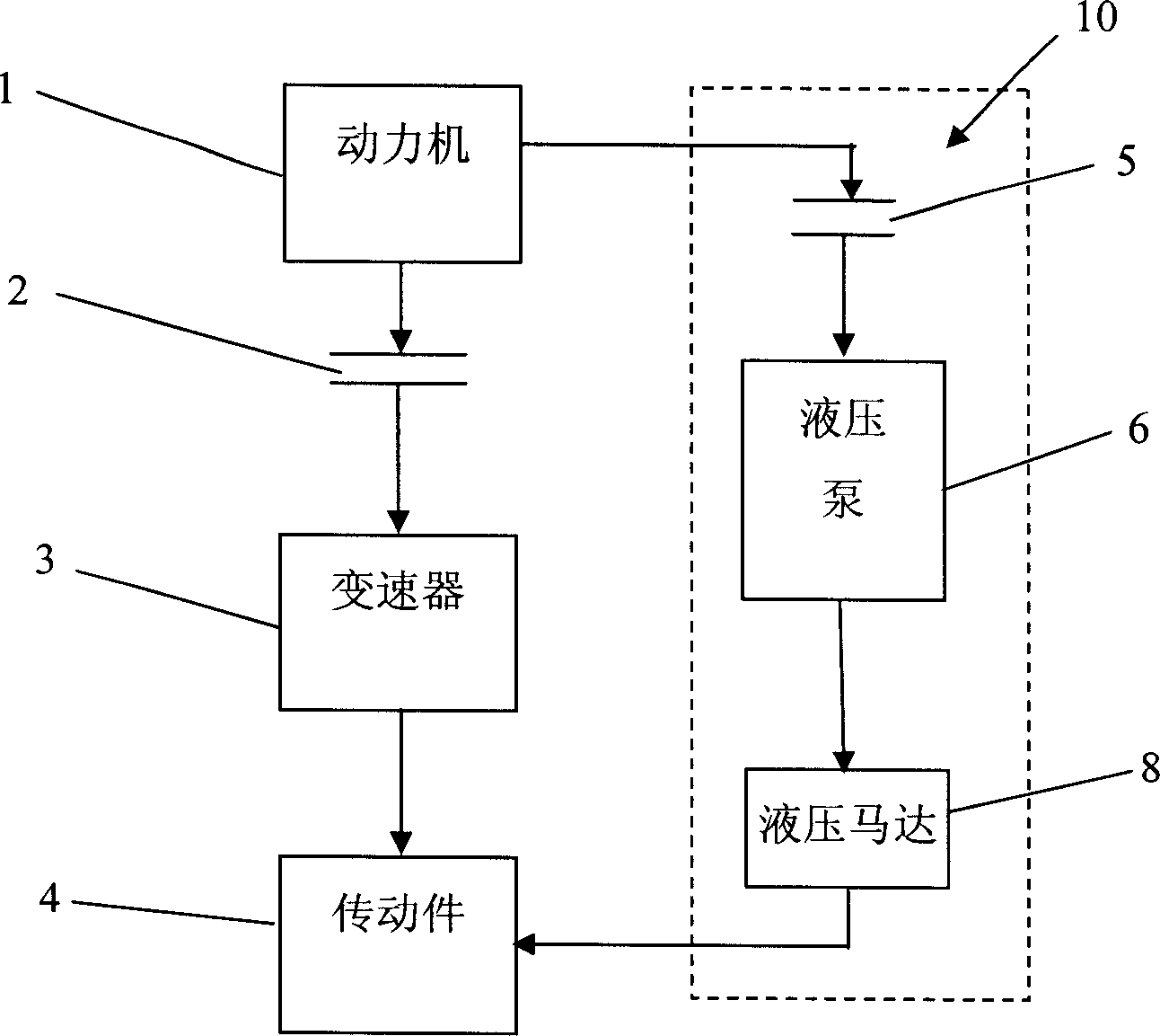
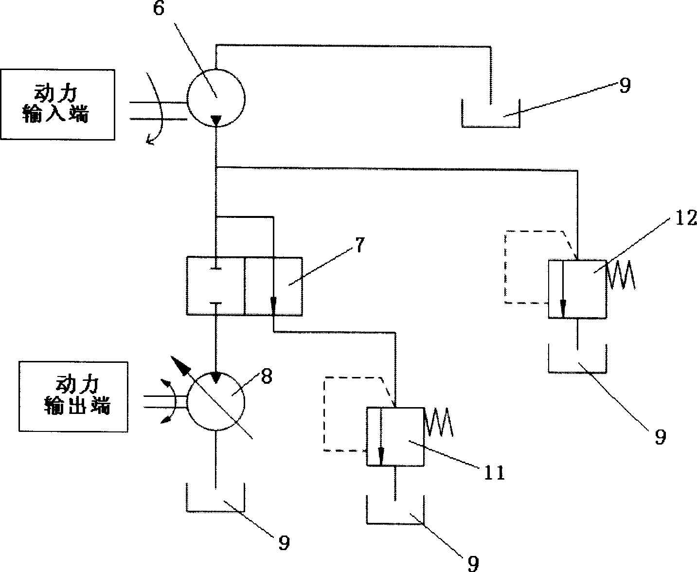
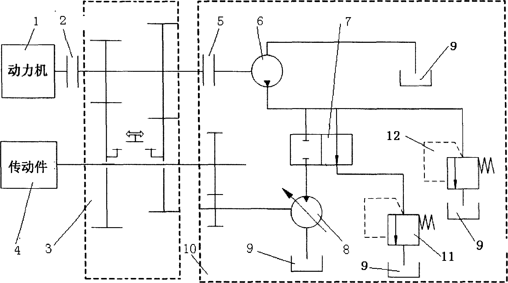
[0030] Such as figure 1 As shown, the transmission device for a motor vehicle provided by the present invention includes a power machine 1, a main clutch 2, a transmission 3 and a transmission member 4 connected sequentially in the order of power transmission. In addition, the transmission device also includes an auxiliary power system 10. The power system 10 includes an auxiliary clutch 5 connected to the power machine 1 , a hydraulic pump 6 connected to the auxiliary clutch 5 , and a hydraulic motor 8 connected to the hydraulic pump 6 and the transmission member 4 .

[0031] Among them, the power machine 1, the main clutch 2, the speed changer 3 and the transmission member 4 connected successively in the order of power transmission can refer to various data on automobile structure, such as "Automotive" published by Tsinghua University Press in...


PUM


Abstract

A speed variator system for motor-driven vehicle is sequentially composed of power unit, master clutch, speed variator, drive unit, and a secondary power unit consisting of secondary clutch, hydraulic pump and hydraulic motor. Its method is also disclosed, which features that the power is continuous in the procedure of speed variation.

Description

technical field [0001] The invention relates to a transmission device of a motor vehicle and a transmission method thereof. Background technique [0002] In a traditional motor vehicle, the transmission system generally includes a power machine, a clutch, a transmission, a transmission member (including the output shaft of the transmission, a universal joint and a drive shaft) and a drive axle (including the final drive, Differentials, axle shafts and transaxle cases). The speed change process of the vehicle is: the driver depresses the clutch pedal to disengage the clutch to cut off the transmission line between the power machine and the driving wheel, and then uses the shift control handle to adjust the gear set in the transmission from one set of meshes to another set of meshes. Afterwards, the clutch pedal is released, the clutch is engaged, and the disconnected transmission line is reconnected, and the power is transmitted from the power machine to the universal transm...

Claims


Application Information

Patent Timeline
Patent Type & Authority Applications(China)
IPC IPC(8): B60K17/00
Inventor 陈伟
Owner BYD CO LTD
Learn More