Reoriented overheat air vent for reducing NO2 produced from coal powder burner

An air port and burner technology, which can be applied in the direction of combustion type, combustion equipment, combustion method, etc., can solve problems such as increasing cost

Inactive Publication Date: 2006-12-06
THE BABCOCK & WILCOX CO
View PDF3 Cites 9 Cited by
  • Summary
  • Abstract
  • Description
  • Claims
  • Application Information

AI Technical Summary

Problems solved by technology

However, this requires additional space in the upper furnace zone of the furnace chamber 10
Increased cost du

Method used


Image

  • Reoriented overheat air vent for reducing NO2 produced from coal powder burner
  • Reoriented overheat air vent for reducing NO2 produced from coal powder burner
  • Reoriented overheat air vent for reducing NO2 produced from coal powder burner

Examples


Embodiment Construction

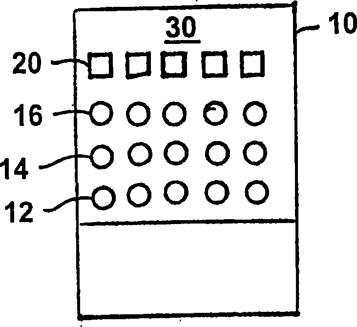
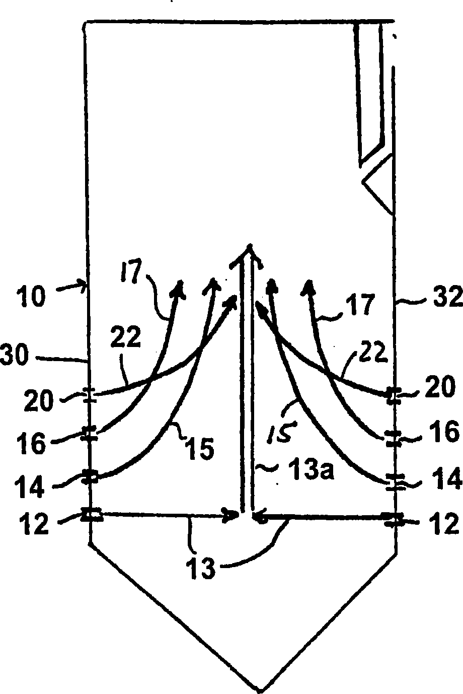
[0029] Referring now to the drawings, wherein like reference numerals are used throughout the seven figures to refer to identical or functionally similar elements, Figure 3-6 Each shows a cavity 10 of an opposed wall furnace comprising the OFA configuration of the present invention. and figure 1 and 2The oven cavity 10 is shown as in the Figure 3-6 In each of the drawings, three burner layers 12, 14, 16 are provided on the front and rear walls 30, 32, respectively. However, as those skilled in the art will appreciate, the present invention is applicable to single-wall and opposed-wall furnace cavities 10 having fewer or more burner layers.

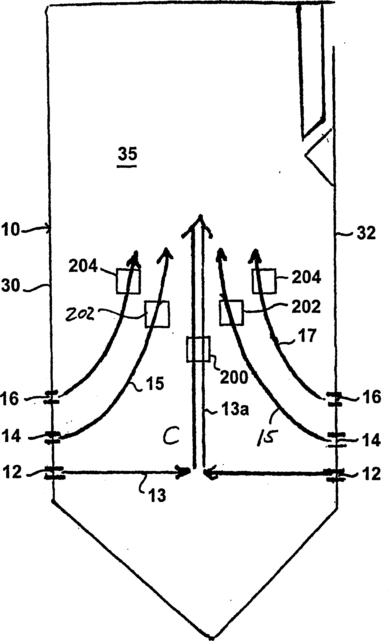
[0030] image 3 Here, the superheated air ports 200 , 202 , 204 are located in the side walls 35 instead of the front or rear walls 30 , 32 . The OFA ports 200, 202, 204 are arranged such that the jet air may generally transversely intersect the flame passages 13a, 15, 17, respectively. That is, the lower OFA port 200 will inject ...


PUM


Abstract

The present invention relates to an overfired air (OFA) nozzle for coal powder boiler or furnace; said overfire air (OFA) nozzle can be used for injecting overfined air (OFA) from side wall so as to increase stationary time of burner layer. Said invention can use several OFA nozzles, and said OFA nozzles can be vertically and horizontally alternatively arranged, so that in the proper time and position the overfired air can be effectively inputted into the burner flame so as to effectively reduce formation of fuel NOx. Said invention also provides the OFA structure for single-wall type or opposed-wall type boiler and furnace.

Description

technical field [0001] The present invention generally relates to the field of industrial and power station furnaces and boilers, and in particular to novel and useful systems that can effectively reduce NO X The product's superheated air (OFA) port configuration for pulverized coal fired furnaces or boilers. Background technique [0002] NO X is an unintended by-product from the combustion of fossil fuels such as coal. Many industrial furnaces and boilers burn pulverized coal as the primary fuel. NO has been found X Emissions have a negative impact on the environment, so NO X Emissions are regulated. [0003] Most of the NO in pulverized coal fired furnaces and boilers X All are formed during the combustion of fossil fuels. this part NO X The formation is called fuel NO X . fuel NO X It is formed by oxidation resulting from the combination of fuel and oxygen during devolatilization and charburnout. [0004] One known for many years to reduce NO X An efficient w...

Claims


Application Information

Patent Timeline
IPC IPC(8): F23C7/04F23C5/08
Inventor A·D·劳鲁
Owner THE BABCOCK & WILCOX CO
Why Eureka
Try Eureka