Closed photo catalyst carrier structure and pollutants treatment system thereof
A photocatalyst and closed technology, which is applied in the field of closed photocatalyst carrier structure and its pollutant treatment system, can solve the problems of weak processing capacity, reducing the contact probability of pollutants and photocatalyst, and small fluid resistance.
- Summary
- Abstract
- Description
- Claims
- Application Information
AI Technical Summary
Problems solved by technology
Method used
Image
Examples
Embodiment 1
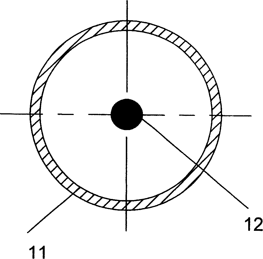
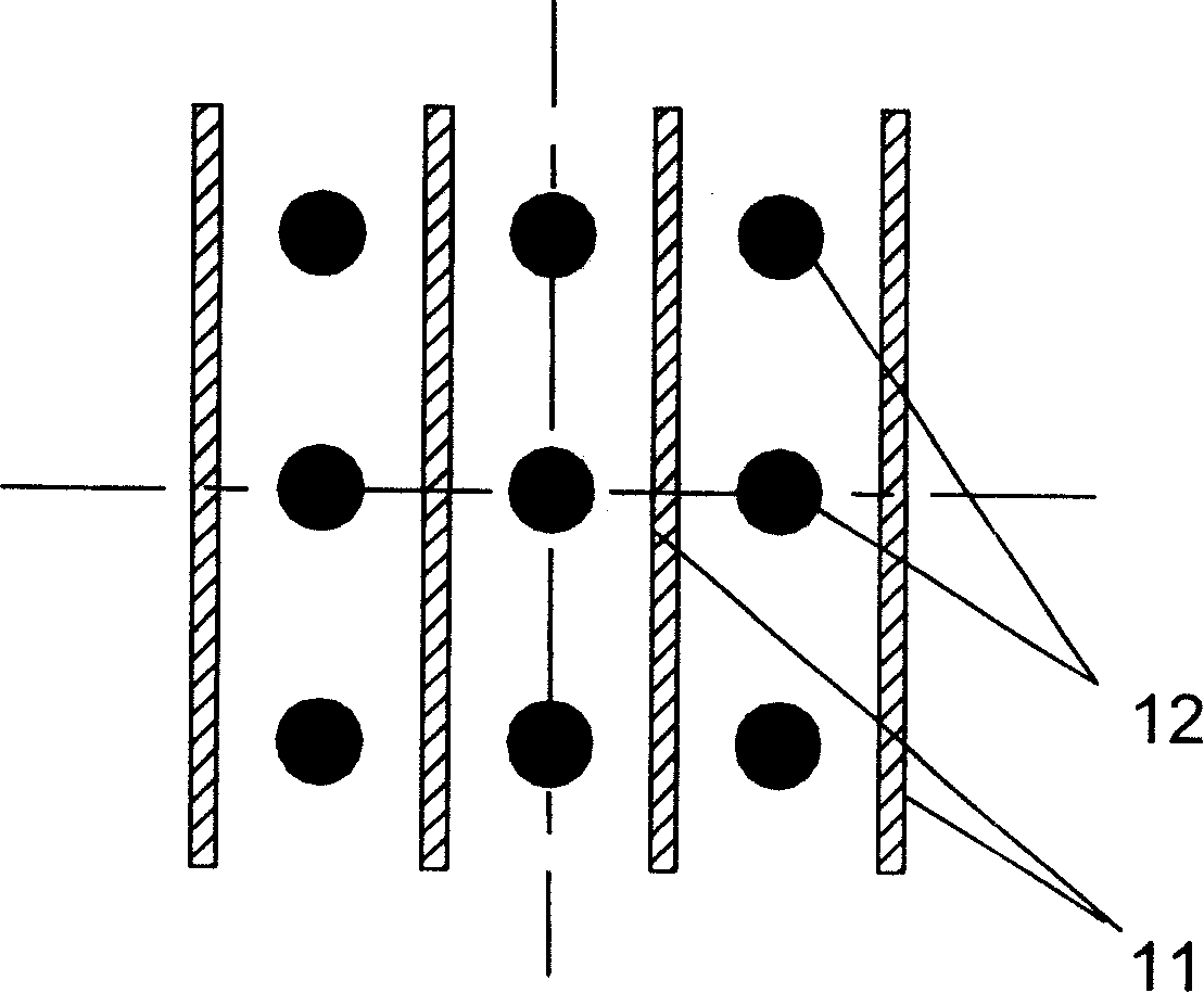
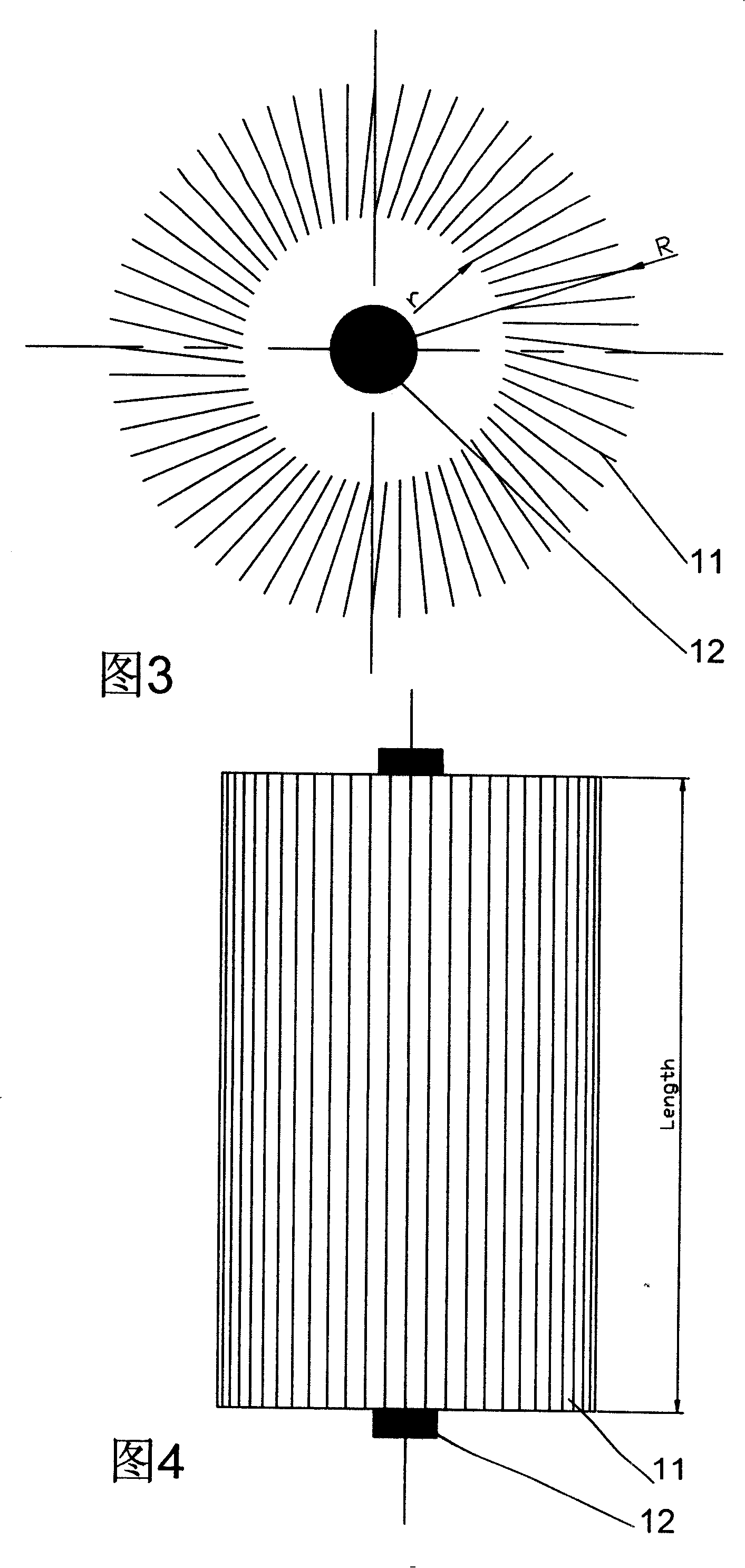
[0046] In embodiment 1 shown in Fig. 10, photocatalyst carrier structure comprises photocatalyst carrier structural part 10 and barrier plate 14, and catalyst carrier structural part 10 comprises several photocatalyst carrier porous material sheets 11 and ultraviolet light source 12, and barrier plate 14 is arranged on photocatalyst On both sides of the gap formed between the carrier porous material sheet 11, when the pollutant fluid flows from the A side of the photocatalyst carrier structural part 10 to the B side, due to the blocking effect of the barrier plate 14, the pollutant fluid does not flow from the photocatalyst carrier porous material sheet. 11 directly pass through the gap formed between them, but flow through the pores of the photocatalyst carrier porous material sheet. In this embodiment, the barrier plate 14 is disposed on one side of the thin plate 11 and forms a semi-closed cavity with the thin plate 11 . The photocatalyst carrier structure part 10 is an axi...
Embodiment 2
[0048] In embodiment 2 shown in Fig. 11, photocatalyst carrier structure comprises photocatalyst carrier structural parts 10 and barrier plate 14, and photocatalyst carrier structural part 10 comprises some photocatalyst carrier porous material sheets 11 and ultraviolet light source 12, and barrier plate 14 is arranged on photocatalyst carrier On both sides of the gap formed between the porous material sheet 11, when the pollutant fluid flows from the A side of the photocatalyst carrier structural part 10 to the B side, due to the blocking effect of the barrier plate 14, the pollutant fluid does not flow from the photocatalyst carrier porous material sheet. 11 directly pass through the gap formed between them, but flow through the pores of the photocatalyst carrier porous material sheet 11. In this embodiment, the barrier plate 14 is disposed on one side of the thin plate 11 and forms a semi-closed cavity with the thin plate 11 . The photocatalyst carrier structure component 1...
Embodiment 3
[0050] In embodiment 3 shown in Figure 12, the photocatalyst carrier structure comprises photocatalyst carrier structural parts 10 and barrier plate 14, and photocatalyst carrier structural part 10 comprises some photocatalyst carrier porous material thin plates 11 and ultraviolet light source 12, and barrier plate 14 is arranged on photocatalyst On both sides of the gap formed between the carrier porous material sheet 11, when the pollutant fluid flows from the A side of the photocatalyst carrier structure 10 to the B side, due to the blocking effect of the barrier plate 14, the pollutant fluid does not flow from the photocatalyst carrier porous material sheet 11 directly pass through the gap formed between them, but flow through the pores of the photocatalyst carrier porous material sheet. In this embodiment, the barrier plate 14 is disposed on one side of the thin plate 11 and forms a partly fully closed and partly semi-closed cavity with the thin plate 11 . The photocataly...
PUM
 Abstract
Description
Claims
Application Information
 - R&D
- Intellectual Property
- Life Sciences
- Materials
- Tech Scout
- Unparalleled Data Quality
- Higher Quality Content
- 60% Fewer Hallucinations
Browse by: Latest US Patents, China's latest patents, Technical Efficacy Thesaurus, Application Domain, Technology Topic, Popular Technical Reports.
© 2025 PatSnap. All rights reserved.Legal|Privacy policy|Modern Slavery Act Transparency Statement|Sitemap|About US| Contact US: help@patsnap.com


