
Electromagnetic flowmeter powered by battery

An electromagnetic flowmeter and battery technology, which is applied in the application of electromagnetic flowmeters to detect fluid flow, volume/mass flow generated by electromagnetic effects, etc. It can solve the problem of places where the power supply cannot be installed and used, the circuit design is unreasonable, and the work place is limited. Large and other problems, to achieve the effect of wide range of use, easy promotion, and reasonable circuit layout

Inactive Publication Date: 2006-12-06
ZHEJIANG DIYUAN INSTR
View PDF2 Cites 7 Cited by
  • Summary
  • Abstract
  • Description
  • Claims
  • Application Information

AI Technical Summary

Problems solved by technology

[0005] The present invention mainly solves the complex structure and unreasonable circuit design in the prior art, the need to use an external power supply to work normally, and the limitations of the workplace. Technical issues such as installation and use; provide a battery-powered electromagnetic flowmeter with simple structure, reasonable circuit layout, self-supply power supply, application in various occasions, wide application range, easy promotion, and direct display of the flow rate of the measured medium on site

Method used


Image

  • Electromagnetic flowmeter powered by battery
  • Electromagnetic flowmeter powered by battery

Examples


Embodiment

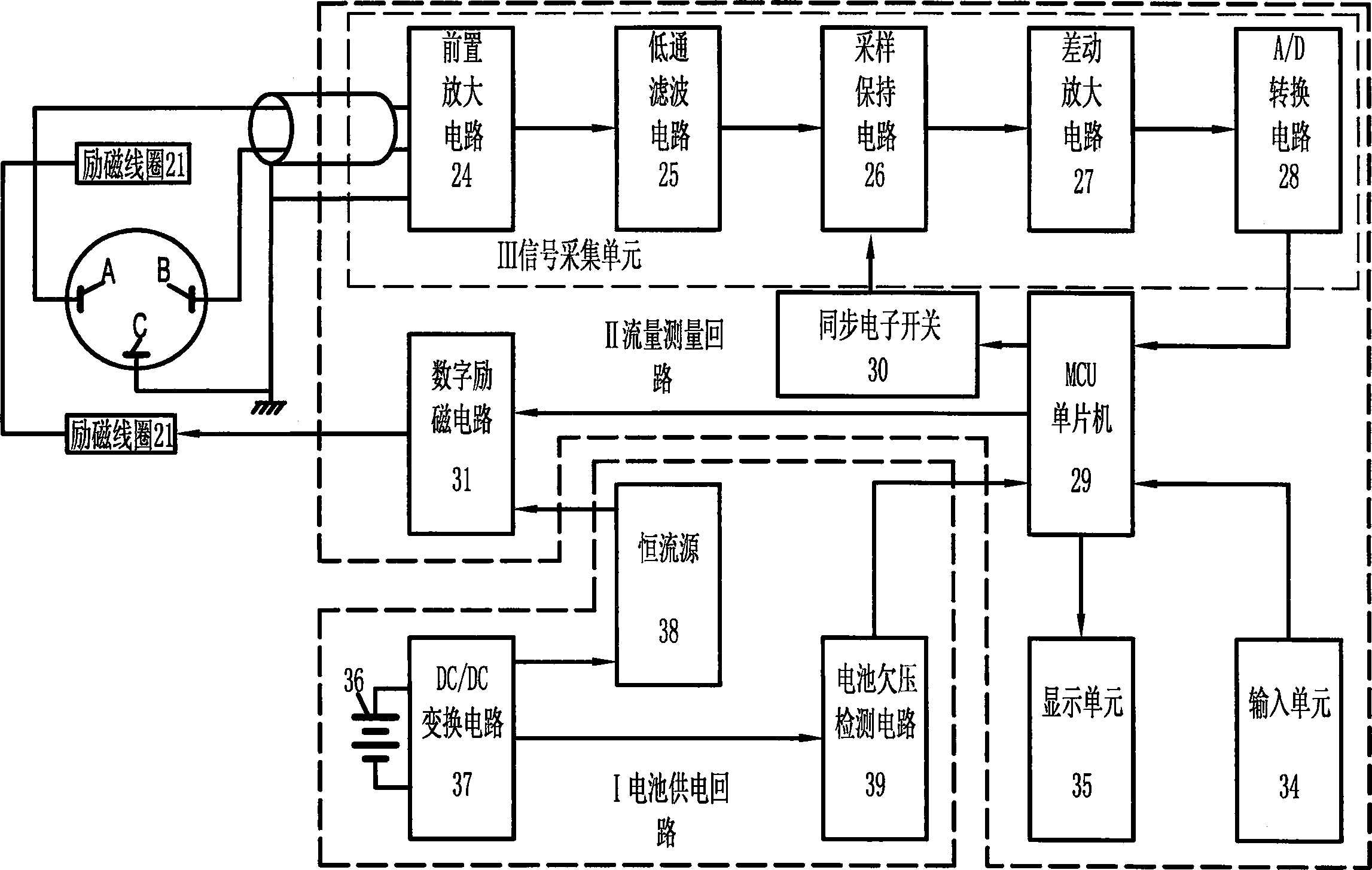
[0020] Embodiment: a battery-powered electromagnetic flowmeter, including an excitation coil 21, a flow measurement circuit II connected to the excitation coil 21, the flow measurement circuit II is connected to the electrode assembly, and the signal acquisition unit III of the flow measurement circuit II receives the signal input by the excitation coil 21 Input to the single-chip microcomputer 29, the flow measurement circuit II is connected with the battery power supply circuit I built in the electromagnetic flowmeter. The battery 36 of the battery power supply circuit 1 is connected with a DC / DC conversion circuit 37, and the DC / DC conversion circuit 37 is connected with a constant current source 38, and the constant current source 38 is connected with a digital excitation circuit 31. The battery 36 of the battery power supply circuit 1 is also connected with a voltage undervoltage detection circuit 39, and the voltage undervoltage detection circuit 39 is connected with the ...


PUM


Abstract

The invention relates to battery feed electromagnetic flow meter structure improvement. It includes exciting coil, flow measurement circuit, and electrode pack. They are connected with each other. The signal collection unit of the flow measurement circuit inputs the signal from the exciting coil to single-chip microcomputer. Its feature is that the flow measurement circuit is connected with battery feed circuit in electromagnetic flow meter. And it has the advantages of simple structure, wide using range, and stable power supply.

Description

technical field [0001] The invention relates to an electromagnetic flowmeter, in particular to a structural improvement of a battery-powered electromagnetic flowmeter. Background technique [0002] In the existing electromagnetic flowmeter technology, there are many types of specific circuit structures, but there are no more than two power supply forms. One is to use an external AC 220V power supply for power supply, which is converted to multiple flowmeters by stepping down the power transformer or switching power supply circuit. One group of working voltages is used for the measurement circuit; the other is powered by a DC 24V power supply, which is converted into multiple groups of working voltages by the power conversion circuit for use by the measurement circuit. [0003] For example, the Chinese utility model patent literature discloses an intelligent electromagnetic flowmeter (application number: 02208234.4), which includes a sensor, an excitation circuit, a microcomp...

Claims


Application Information

Patent Timeline
Patent Type & Authority Applications(China)
IPC IPC(8): G01F1/58
Inventor 孙向东叶建军
Owner ZHEJIANG DIYUAN INSTR
Learn More