

Technique for riveting base plate of radiator and fins
A heat sink and fin technology, which is applied in the field of riveting technology of the bottom plate of the heat sink and fins, can solve the problems that the forming mold is easy to break, the heat sink cannot meet the industrial economic benefits, and the cost is high
- Summary
- Abstract
- Description
- Claims
- Application Information
AI Technical Summary
Problems solved by technology
Method used
Image

Examples
Embodiment Construction
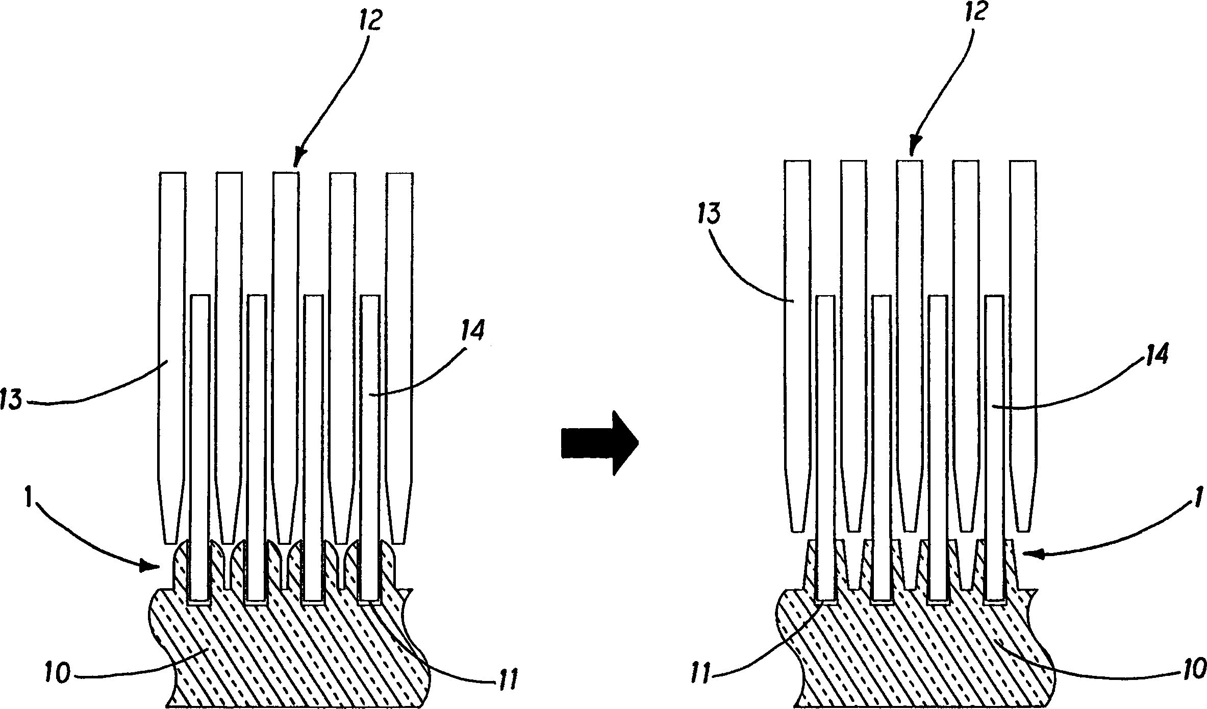
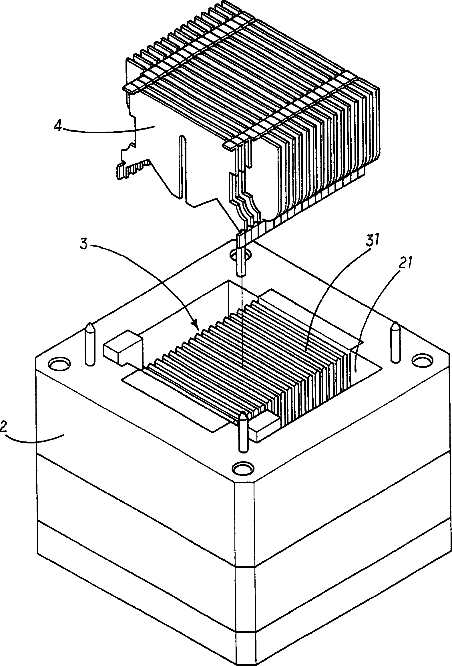
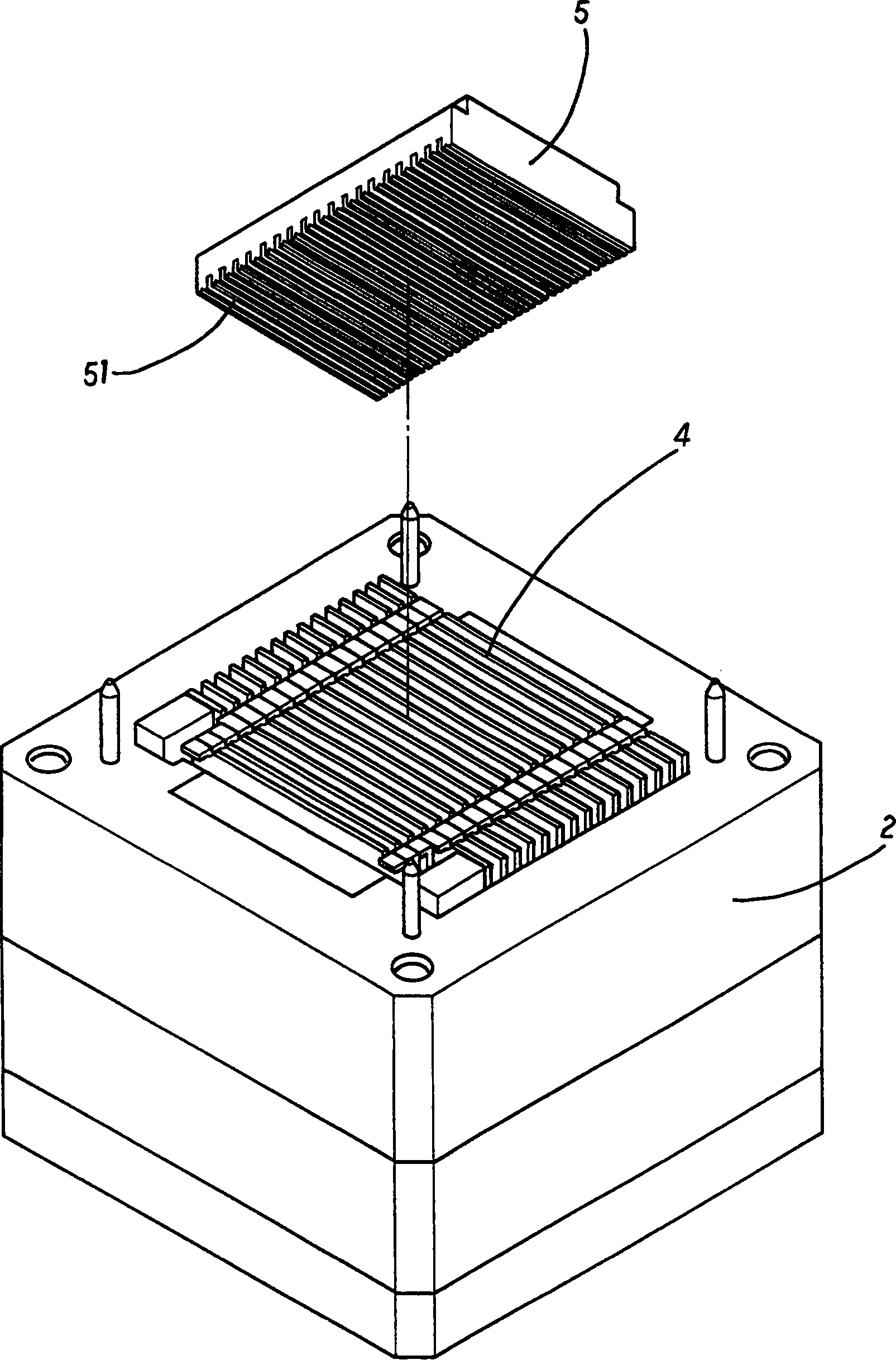
[0024] See first Figure 2 ~ Figure 3 As shown, the riveting process of a radiator base plate and fins in the present invention includes a jig 2, the jig 2 is formed with a hollow 21, and the forming mold 3 is installed in the hollow 21 of the jig 2, and the molded The mold 3 is integrally provided with a plurality of punches 31 arranged in sequence. The punches 31 are extended from the molding die 3 to have a predetermined height. The fins 4 are composed of a plurality of fins. The operation is combined into a single body, there is a predetermined gap between adjacent fins 4, and the fins 4 can be inserted into the molding die 3 for positioning, so that the fins 4 and the punches 31 are adjacent to each other, and a bottom plate 5, its surface A corresponding groove 51 is formed at the joint end of the fin 4, and the bottom plate 5 is positioned on the jig 2 (such as Figure 4 ), the fins 4 have to be plugged in correspondingly with the grooves 51, and the punches 31 are clo...
PUM
 Abstract
Description
Claims
Application Information