

Evaporation mixing combustion mode for liquid fuel and combustion chamber therefor
A liquid fuel, mixed combustion technology, applied in the direction of combustion chamber, combustion method, combustion equipment, etc., can solve the problems of air pollution, insufficient combustion, etc., and achieve the effect of sufficient fuel combustion, reasonable combustion method and less exhaust gas
- Summary
- Abstract
- Description
- Claims
- Application Information
AI Technical Summary
Problems solved by technology
Method used
Image

Examples
Embodiment Construction
[0017] The present invention will be further described below in conjunction with the accompanying drawings and embodiments.
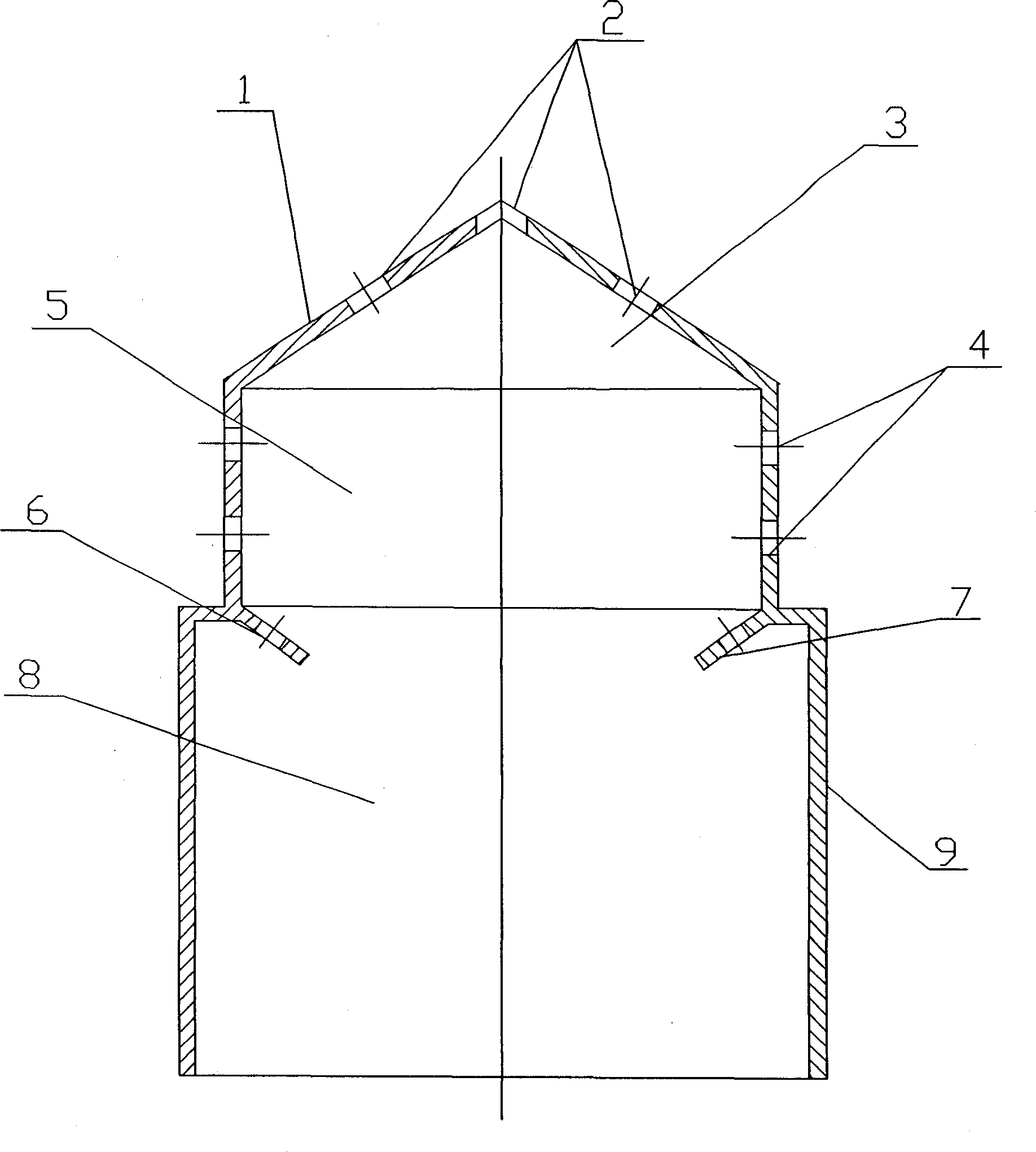
[0018] figure 1 , the combustion chamber 9 is divided into three areas: evaporation zone 3, mixing zone 5 and combustion zone 8. The fuel is gasified in the evaporation zone 3, which is brought into the evaporation zone 3 by the primary air, and then through a reasonable secondary air organization, the gasified liquid fuel is fully mixed in the mixing zone 5, and mixed The zone 5 is close to the auto-ignition temperature, and by setting the necking plate 7 and the vent hole 6 between the mixing zone 5 and the combustion zone 8, the fuel can achieve homogeneous lean combustion in the combustion zone 8, thereby controlling Nox pollution The generation of things.
[0019] The evaporation zone 3 is near the closed end of the combustion chamber 9 and is mainly the area where the fuel evaporates or gasifies. At the closed end of the combustion chamber 9, t...
PUM
 Abstract
Description
Claims
Application Information