Tooth roller furnace biomass particle removal burning boiler

A toothed roller furnace, material technology, applied in the field of biomass fuel combustion equipment, to achieve the effects of high heat energy utilization, sufficient fuel combustion, and high combustion efficiency

Inactive Publication Date: 2015-05-20
杨俊栋
View PDF6 Cites 0 Cited by
  • Summary
  • Abstract
  • Description
  • Claims
  • Application Information

AI Technical Summary

Problems solved by technology

[0004] In order to overcome the defects of the existing biomass particle fuel combustion,

Method used


Image

  • Tooth roller furnace biomass particle removal burning boiler
  • Tooth roller furnace biomass particle removal burning boiler
  • Tooth roller furnace biomass particle removal burning boiler

Examples


Embodiment Construction

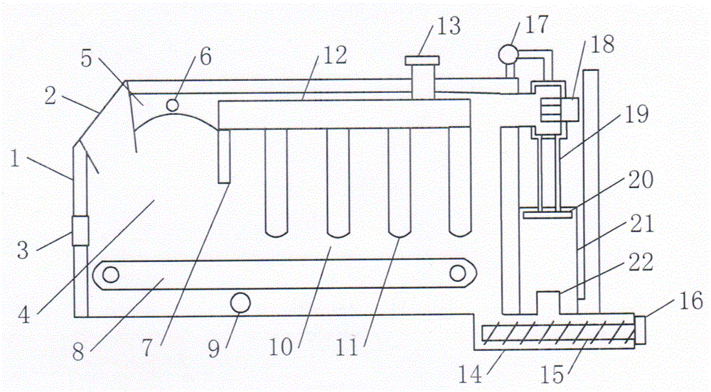
[0012] As shown in the figure, a front observation door 3 is provided on the front wall of the furnace body 1, a fuel inlet 2 is provided on the upper side of the front part of the furnace body, and a baffle 7 is arranged in the furnace body. As the front combustion chamber 4, the upper part of the front combustion chamber is provided with an arched furnace arch 5, and the furnace arch is provided with a vent 6. The main combustion chamber 10 is formed between the rear side of the baffle plate and the rear furnace body wall. A vertical heat exchange tube 11 is installed between the indoor and the water jacket wall of the furnace body. The upper end of the heat exchange tube is connected to the thermal medium concentration chamber 12 arranged in the furnace body, and the thermal medium output is connected to the upper part of the thermal medium concentration chamber. Pipe 13 is provided with a pressure water source pipe 17 on the upper part or one side of the furnace body. The p...


PUM


Abstract

The invention provides a tooth roller furnace biomass particle removal burning boiler. An exhaust fan and a dust remover are arranged on the back part of a furnace body, the dust remover is communicated with a residue removal pool, the residue removal pool is arranged on the lower portion of the back of the furnace body, the residue removal pool is internally provided with a residue removal solenoid, a front burning chamber and a main burner are arranged in the furnace body, and the burning chamber is internally provided with a pin roll fire grate. The tooth roller furnace biomass particle removal burning boiler has the advantages that fuel full burn, the ventilation is good, and the integration of the dust removal and the residue removal is realized, and therefore the combustion efficiency is high, the heat energy utilization is high, and the effect of energy conservation and environmental protection are realized. The tooth roller furnace biomass particle removal burning boiler is applicable to being used as a biomass particle removal burning boiler.

Description

technical field [0001] The invention provides a biomass fuel combustion equipment, specifically a toothed roller grate biomass particle combustion boiler. Background technique [0002] At present, biomass pellet fuel boilers usually use several combustion methods: one is the biomass gasification furnace, which is difficult to control and is easy to emit smoke and cause secondary pollution; The combustion process is completed at the same time as the secondary combustion. The problem is that due to the difference in fuel materials, the utilization rate of biomass fuel will be wasteful. When the fuel slag is in a molten state, it is easy to generate slagging blocks to block the channel, causing subsequent fuel to accumulate. , resulting in operational failure; the third is the spiral propulsion counter-burning furnace, the slag removal needs to be done manually, it cannot be automated, and the operation is difficult, which is easy to cause personal injury. [0003] Existing b...

Claims


Application Information

Patent Timeline
IPC IPC(8): F24H1/24F23B10/02F23J15/04
Inventor 杨俊栋
Owner 杨俊栋
Why Eureka
Try Eureka