Laser detection apparatus and method for in-furnace information

A laser detection and laser technology, used in measuring devices, optical devices, optical testing flaws/defects, etc., can solve problems such as inability to comprehensively observe the operation of equipment in the furnace, the charging process and the condition of the material surface.

Inactive Publication Date: 2006-12-13
SHENVANG PAJONIIR TEK CORP BEJDZHING +1
View PDF3 Cites 24 Cited by
  • Summary
  • Abstract
  • Description
  • Claims
  • Application Information

AI Technical Summary

Problems solved by technology

In addition, the wall observation device disclosed in CN1347492A can only be used to observe the damage of the furnace wall, but cannot comprehensively observe the information in the furnace, such as the operation of the equipment in the furnace, the charging process and the state of the material surface, etc.

Method used


Image

  • Laser detection apparatus and method for in-furnace information
  • Laser detection apparatus and method for in-furnace information
  • Laser detection apparatus and method for in-furnace information

Examples


Embodiment Construction

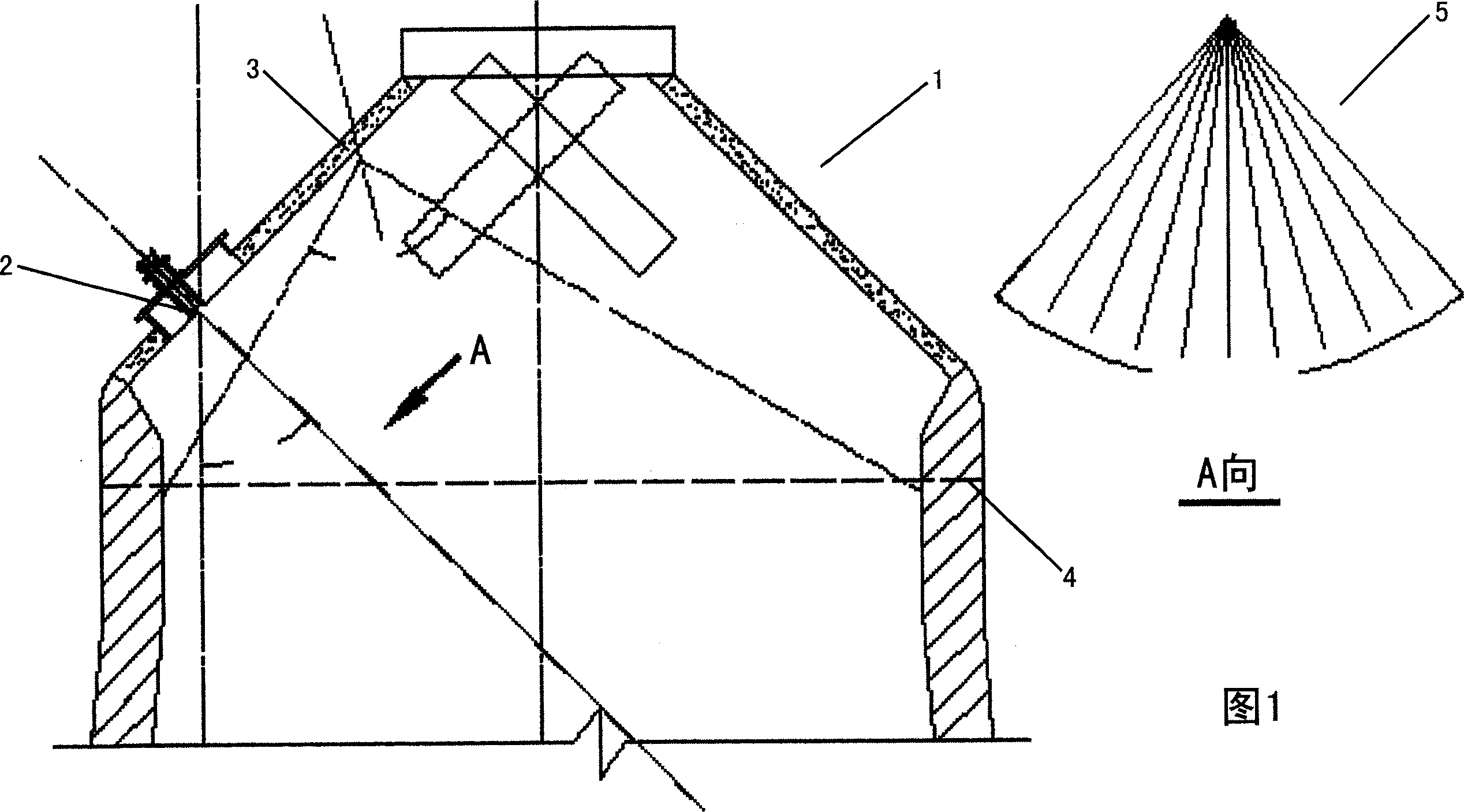
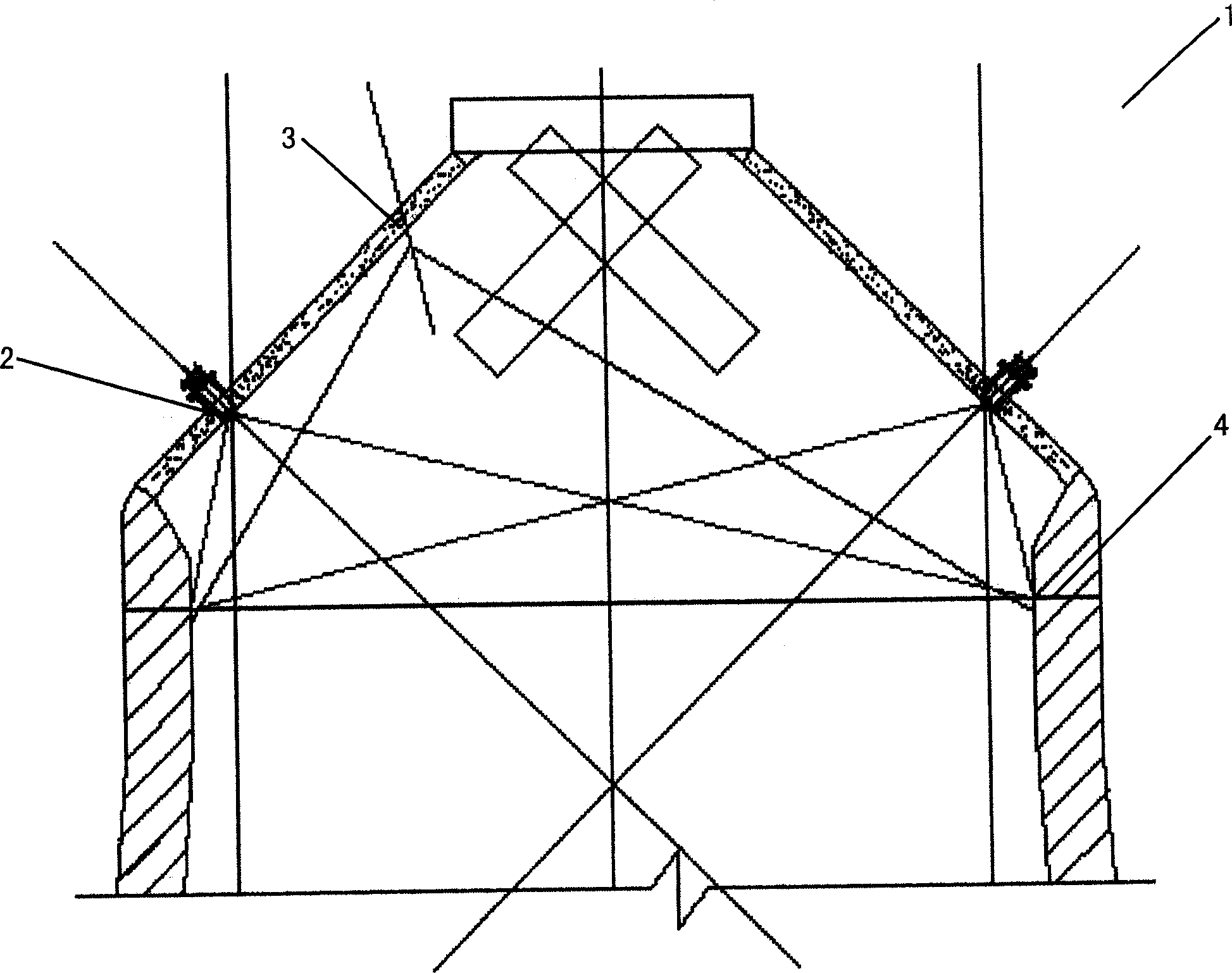
[0013] See Figure 1 and figure 2 , an industrial furnace such as a blast furnace 1 is provided with a laser inlet 2 and a camera 3 above the reference material surface 4, and the laser inlet 2 and the camera 3 are arranged on the blast furnace 1 in an appropriate manner, that is, under normal circumstances, the inside of the blast furnace will not pass The laser entrance 2 and the video camera 3 are in communication with the outside world, and the video camera 3 can acquire the required images inside the furnace formed by the laser 5 . One or more laser entrances 2 and / or cameras 3 can be provided as required. It should be noted that the laser (not shown) can be arranged outside the blast furnace 1, but also inside it. Due to the high temperature, high pressure, high dust, high humidity and other environments inside the blast furnace, ordinary camera methods cannot obtain information in the furnace at all. However, according to the different production conditions inside the ...


PUM


Abstract

The invention provides a laser detection device for monitoring information inside of the industrial kiln with heavy dust and/or heavy smoke in it. The inventive device comprises a laser device for generating laser light to get into the kiln; a vidicon which is installed on the kiln body for capturing image produced from laser light generated by the laser inside of the kiln, wherein the image includes laser pattern produced during laser light passing through dust and/or smoke. The invention is characterized in that the inventive device can detect information inside of the kiln online, such as operation situation of device, material feeding process and material situation, by means of laser tracing and camera shooting. The invention also provides a laser monitoring method for getting information inside of the kiln.

Description

technical field [0001] The present invention relates to a laser detection device and method for furnace information, more specifically, to a laser detection device and method for the operation of furnace equipment, charging process and material surface status of a closed industrial furnace such as a blast furnace. Background technique [0002] Usually, due to the high temperature, high pressure, high dust, high humidity and other furnace environments in closed industrial furnaces such as blast furnaces, operators can only infer the production and equipment operating conditions in the furnace through the values ​​of conventional detection instruments such as temperature, pressure, and flow. . In order to obtain the required information in the furnace, people have developed scanning types such as infrared scanning, microwave scanning and other detection devices, but this type of scanning detection device requires corresponding receiving instruments and complex computing system...

Claims


Application Information

Patent Timeline
Patent Type & Authority Applications(China)
IPC IPC(8): G01B11/00G01C11/00G01N21/88G01N21/954F27D21/00
Inventor 高征铠杜宪文赵承平曹俊民高永张清崇高泰罗文骥
Owner SHENVANG PAJONIIR TEK CORP BEJDZHING
Why Eureka
Try Eureka