Magnetic signal measurement apparatus

A magnetic field measurement and magnetic field technology, applied in measurement devices, measurement of magnetic variables, magnetic field/electric field shielding, etc., can solve the problems of large incoming volume, low magnetic shielding effect, measurement signal deformation, etc., to reduce deformation and high shielding efficiency. Effect

Inactive Publication Date: 2006-12-13
HITACHI HIGH-TECH CORP
View PDF3 Cites 20 Cited by
  • Summary
  • Abstract
  • Description
  • Claims
  • Application Information

AI Technical Summary

Problems solved by technology

[0007] (1) In Patent Document 1, since both ends of the cylinder are open structures, there is a problem that the shielding effect of the magnetic component in the direction of the cylinder axis is lower than the magnetic shielding effect in the direction perpendicular to the cylinder axis. In particular, if the cylinder If the length of the cylinder is shorter than twice the diameter of the cylinder opening, the amount of magnetism of the vertical component of the cylinder axis will increase from the cylinder opening, and there is a problem that the magnetic shielding effect will be reduced.
[0008] (2) In Patent Document 2, the external magnetic signal is shielded by arranging a high-permeability material near the measurement part, but there is a problem that the original target measurement signal itself is deformed.
In particular, since a signal from a sensor near a high-permeability material bends toward a high-permeability magnetic material, there is a two-dimensional distribution when measuring the magnetic field distribution using a plurality of sensors or inferring the signal source from the distribution. The problem of the change of the pattern or the error of position estimation

Method used


Image

  • Magnetic signal measurement apparatus
  • Magnetic signal measurement apparatus
  • Magnetic signal measurement apparatus

Examples


Embodiment 1

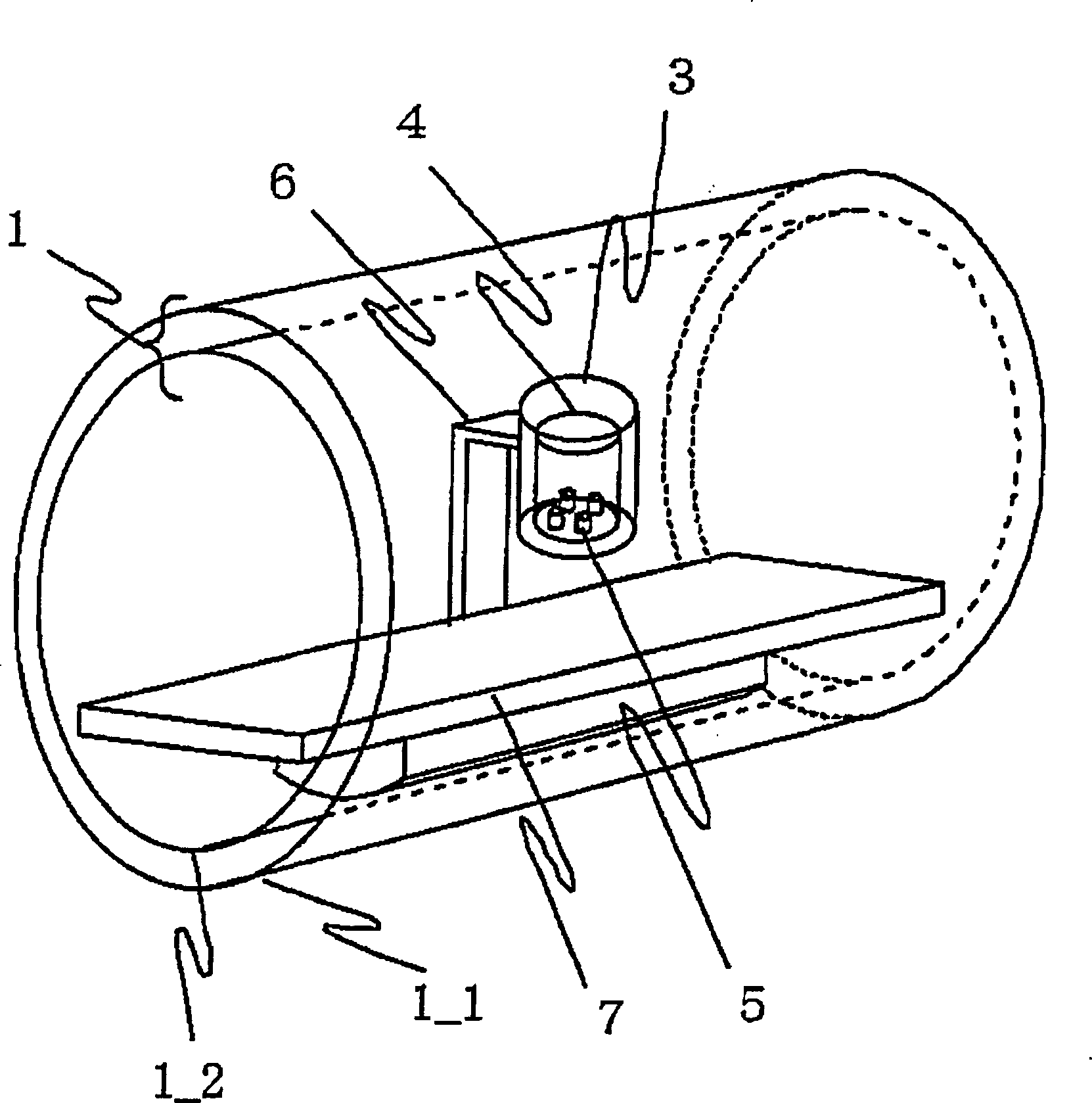
[0025] exist figure 1 In the figure, the first magnetic shielding device 1 has a cylindrical shape, and is a perspective view showing an embodiment in which biomagnetism, mainly a magnetic field emitted from the heart, is measured. The first magnetic shielding device 1 is constituted by a single cylinder or a plurality of open cylinders with different diameters. In Example 1, it consists of the 1st cylinder 11 and the 2nd cylinder 12. The arrangement of each cylinder constituting the first magnetic shielding device 1 is arranged so that the central axis of each cylinder overlaps on the same axis. exist figure 1 The figure shows an example of the case where the number of cylinders constituting the first magnetic shielding device 1 is two, but as a structure, the magnetic shielding rate is determined according to the thickness, length, and cylinder diameter of each cylinder, so the circle The number of cylinders varies depending on the required shielding ratio. As a general ...

Embodiment 2

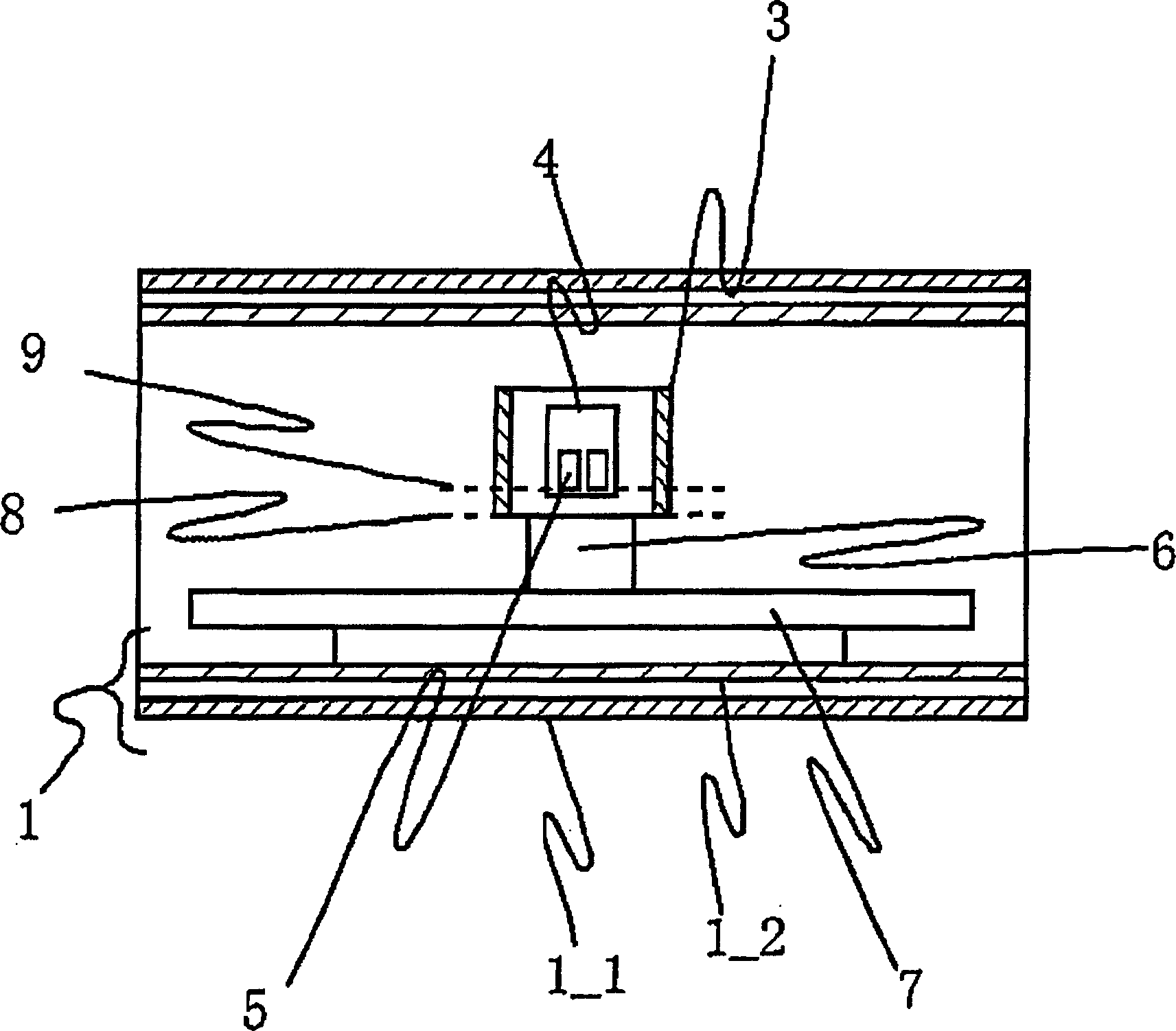
[0037] exist Figure 10 In the figure, the second magnetic shielding device 21 is square column-shaped, and it is a perspective view of an embodiment showing the case of measuring biomagnetism, mainly the magnetic field emitted from the heart. The first magnetic shielding device 1 is constituted by a single cylinder or a plurality of open cylinders with different diameters. In Example 2, it consists of the 1st cylinder 11 and the 2nd cylinder 12. The arrangement of each cylinder constituting the first magnetic shielding device 1 is arranged so that the central axis of each cylinder overlaps on the same axis. exist Figure 10 The figure shows an example of the case where the number of cylinders constituting the first magnetic shielding device 1 is two, but as a structure, the magnetic shielding rate is determined according to the thickness, length, and cylinder diameter of each cylinder, so the circle The number of cylinders varies depending on the required shielding ratio. ...

Embodiment 3

[0040] exist Figure 11 shows a method of dividing the correction region into a plurality of regions, and performing correction by approximating the correction formula to a polynomial of distance in each region. In the figure, the correction area is divided into 3 areas. In the numerical correction performed by the arithmetic unit 35, the radius dr of the second magnetic shielding device 3 is normalized, and the radius dr is set to 1. Divide dr into 3 areas, which are designated as dr in the order from the central axis of the second magnetic shielding device 3 to the cylinder wall 1 、dr 2 、dr 3 . The correction magnetic field in each area is defined as Bz in the order from the central axis of the second magnetic shielding device 3 to the cylinder wall 1 、Bz2 、Bz 3 . Let the distance from the central axis 18 of the second magnetic shielding device 3 to the sensor 5 be ds. Let the value of the magnetic field measured by the sensor 5 be Bz'.

[0041] The correction magne...


PUM


Abstract

If the length of cylinder of magnetic screening arrangement is shorter, the magnetic screening effect is reduced. At the two ends of magnetic-measurement, there is the second magnetic screening arrangement, which is in the first magnetic screening arrangement. The second magnetic screening arrangement can shield the magnetic-field component which the first magnetic screening arrangement can't shield.

Description

technical field [0001] The technical field to which the present invention belongs relates to a magnetic field measuring device that uses a magnetic sensor or an electromagnetic field sensor to measure weak magnetic and electromagnetic wave signals. Background technique [0002] Typically, magnetic shielding is achieved by completely covering an area larger than the measurement area with a material of high magnetic permeability. However, in this case, in the device for measuring the magnetic field generated by the human body, since it is necessary to cover a space larger than the human body with a high magnetic permeability material, it is necessary to have a space as large as 2m×2m×2m (depth, width, height) ) space (for example, Non-Patent Document 1). A high magnetic shielding effect can be obtained in the magnetic shielding device disclosed in Non-Patent Document 1, but a wide installation space is required. For example, when installed in a hospital, there is a problem th...

Claims


Application Information

Patent Timeline
Patent Type & Authority Applications(China)
IPC IPC(8): G01R33/02H05K9/00
CPCG01R33/0005G01R33/0029G01R33/025G01R33/0047
Inventor 铃木大介
Owner HITACHI HIGH-TECH CORP
Why Eureka
Try Eureka