Ambiguity path identifying system and method thereof

A path recognition and ambiguity technology, applied in the field of radio frequency identification, can solve problems such as increasing construction costs, and achieve the effects of fast reading and writing speed, long communication distance, and high sensitivity

Active Publication Date: 2006-12-13
浙江省公路管理局 +1
View PDF0 Cites 39 Cited by
  • Summary
  • Abstract
  • Description
  • Claims
  • Application Information

AI Technical Summary

Problems solved by technology

[0012] The purpose of the present invention is to provide a kind of ambiguity path identification system and its method based on radio frequency identification technology and integr

Method used


Image

  • Ambiguity path identifying system and method thereof

Examples


Embodiment Construction

[0030] The present invention will be described in further detail below in conjunction with the embodiments and accompanying drawings, but the embodiments of the present invention are not limited thereto.

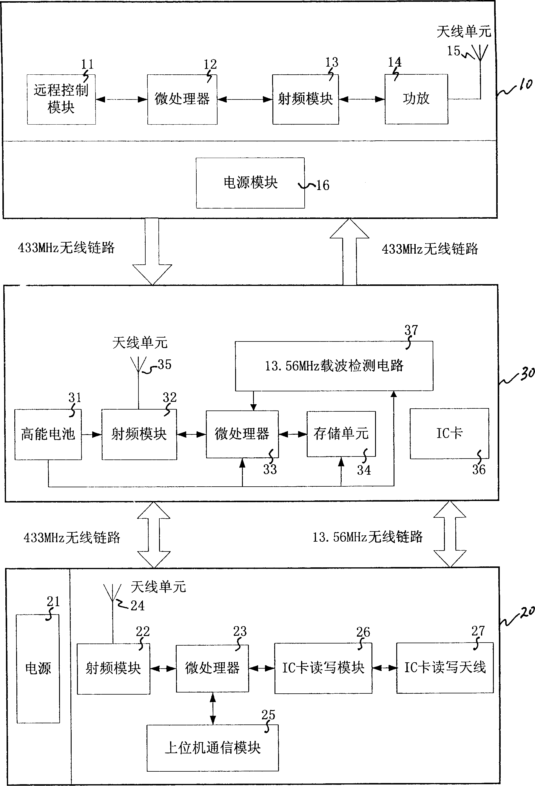
[0031] like figure 1 As shown, the ambiguous path recognition system of the present invention includes a roadside antenna device 10, a desktop reader 20, and a vehicle-mounted unit 30, wherein:

[0032] Described roadside antenna device 10 comprises remote control module 11, microprocessor 12, radio frequency module 13, power amplifier 14, antenna unit 15 and power supply module 16, described microprocessor 12 and radio frequency module 13, remote control module 11 blocks connected separately, the antenna unit 15 is connected to the radio frequency module 13 via the power amplifier 14 . The remote control module 11 is a wired or wireless network communication module, or an RS485 communication module, which is used for the computer to remotely set the path identification inf...


PUM


Abstract

The disclosed ambiguous path recognition system comprises: a road-side antenna device to continual send RF signal with path label information, a table read-write machine to read path information, and a vehicle-carry unit with an IC card to record vehicle path information and a receive and store device for former label information. This invention saves investment, has high reliability, and fit to spread on freeway.

Description

technical field [0001] The invention relates to the technical field of radio frequency identification, in particular to a path identification system and method suitable for a highway toll system. Background technique [0002] Network toll collection is the main development trend of expressway toll collection methods. Basically, all developed regions have implemented expressway network toll collection systems based on IC cards. In the networked toll collection system, accurate account splitting and settlement is the key to ensuring the interests of expressway owners, and complete and clear driving route data is the basis for accurate account splitting. At present, the highway network is becoming more and more developed. In the same road network, starting from the same starting point and arriving at the same destination, there are many different paths (ambiguous paths) to choose from, but the current toll system can only identify the starting point Information and destination...

Claims


Application Information

Patent Timeline
IPC IPC(8): G07B15/00G07B15/06
Inventor 罗瑞发杨成刘咏平李兴锐
Owner 浙江省公路管理局
Why Eureka
Try Eureka