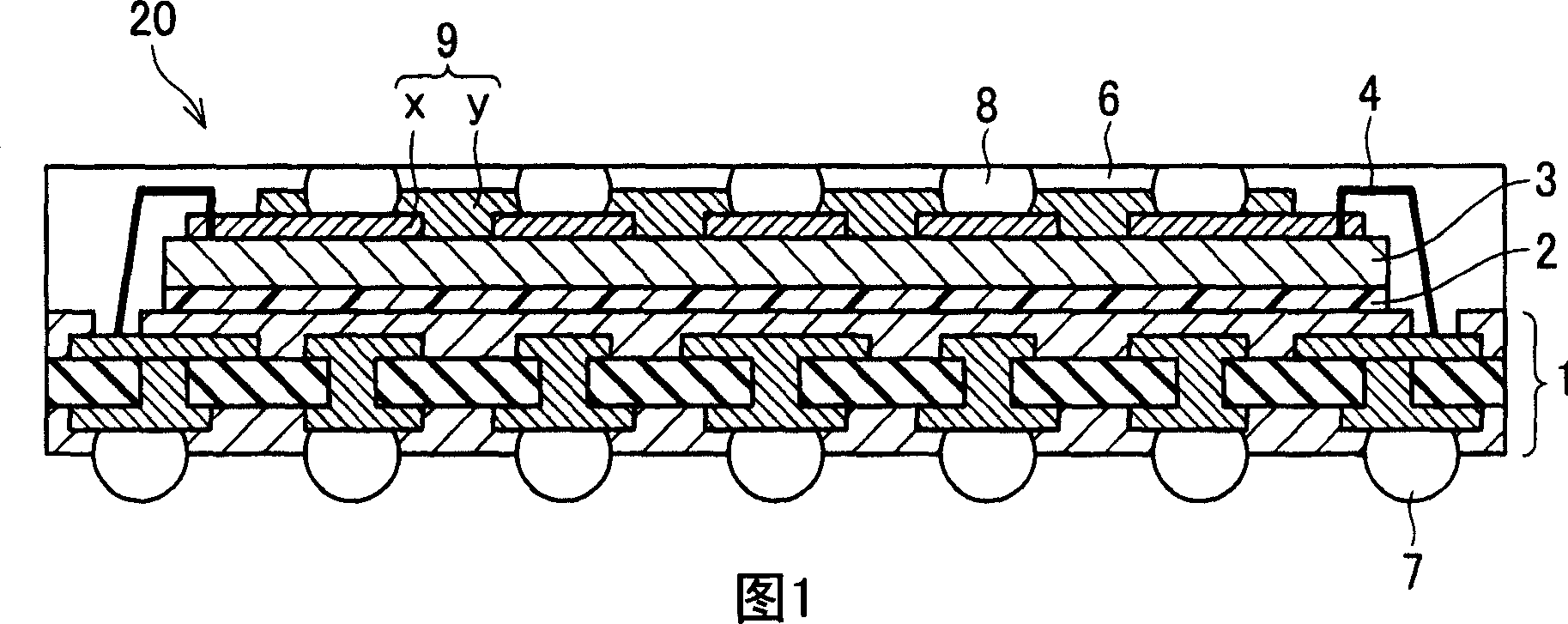
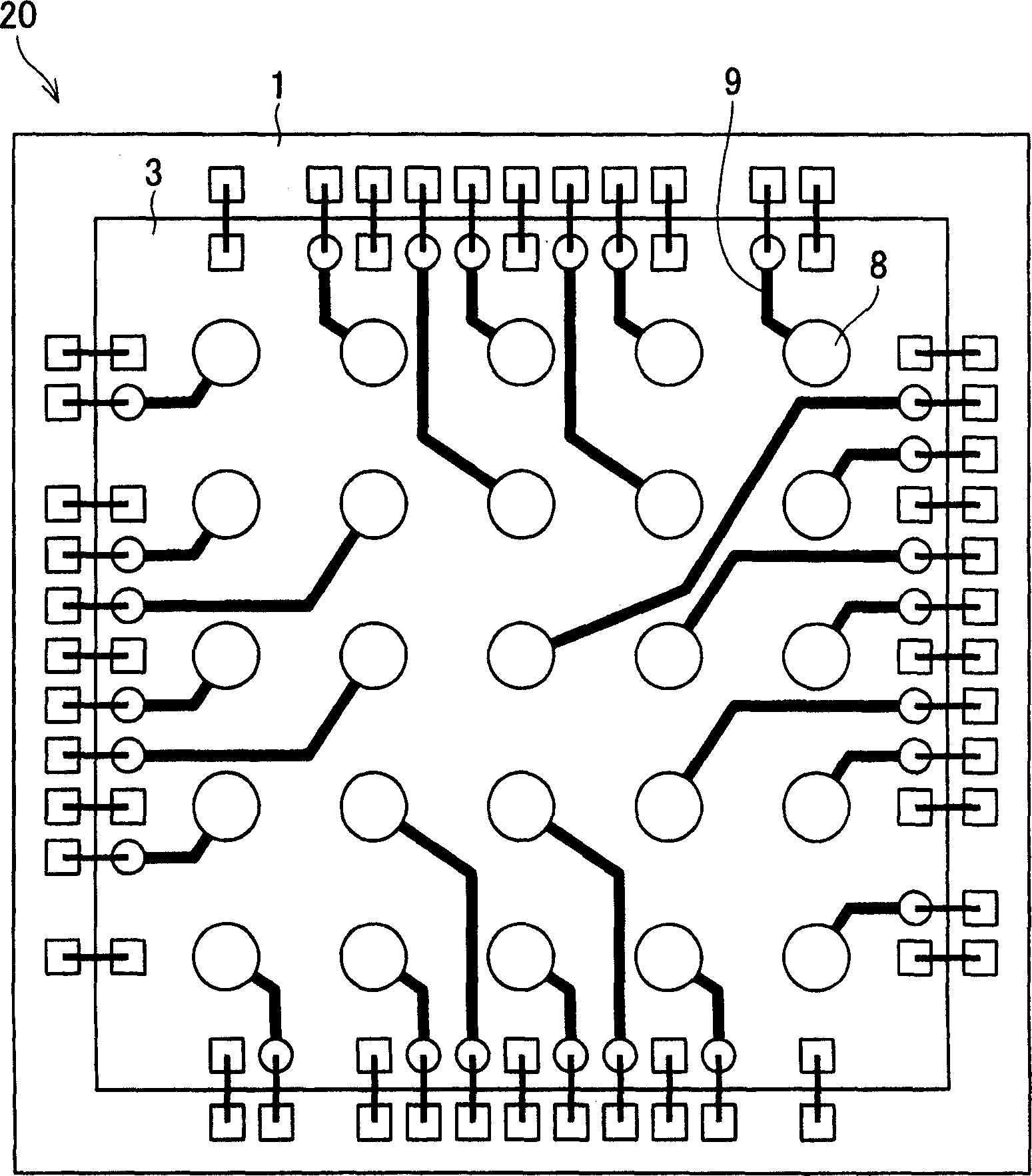
Semiconductor device, stacked semiconductor device, and manufacturing method for semiconductor device

A manufacturing method, semiconductor technology, applied in the direction of semiconductor/solid-state device manufacturing, semiconductor devices, semiconductor/solid-state device components, etc., capable of solving problems such as easy deformation, damage to the semiconductor chip 103, and inability of the wiring layer 108 to fully absorb stress, etc.

Inactive Publication Date: 2006-12-13
SHARP KK
View PDF2 Cites 69 Cited by
  • Summary
  • Abstract
  • Description
  • Claims
  • Application Information

AI Technical Summary

Problems solved by technology

The wiring layer 108 is relatively thin, generally about 50um in thickness, and its material is easily deformed, so the wiring layer 108 cannot completely absorb the stress applied by the mold 50
Therefore, a large stress is applied to the semiconductor chip 103, which may cause damage to the semiconductor chip 103.

Method used


Image

  • Semiconductor device, stacked semiconductor device, and manufacturing method for semiconductor device
  • Semiconductor device, stacked semiconductor device, and manufacturing method for semiconductor device
  • Semiconductor device, stacked semiconductor device, and manufacturing method for semiconductor device

Examples


Deformed example 1

[0061] Figure 4 is a cross-sectional view showing the structure of a semiconductor device 20 a according to Modification 1. FIG. Such as Figure 4 As shown, in the semiconductor device 20a, instead of the connection of the metal wire 4, the semiconductor chip 3 and the substrate 1 are connected by flip-chip connection (Flip-Chip Bond) technology, and the flip-chip connection is through the flange (Bump) 10 to achieve.

[0062] Other than that, the semiconductor device 20a has the same structure as the semiconductor device 20 described above.

[0063] As described above, in the semiconductor device 20a of the present modified example, the semiconductor chips 3 are mounted to the substrate 1 at a higher density by employing the flip-chip connection technique.

[0064] The semiconductor device 20 a of this modified example can be manufactured by the same method as the manufacturing method of the semiconductor device 20 described above except that the semiconductor chip 3 and ...

Deformed example 2

[0066] Figure 5 is a cross-sectional view showing the structure of a semiconductor device 20b according to Modification 2. In the aforementioned semiconductor device 20 , semiconductor device 20 a, the wiring layer 9 is formed directly on the semiconductor chip 3 . However, in the semiconductor device 20b, as Figure 5 As shown, the wiring layer 9 is formed on the support body 11 and mounted on the semiconductor chip 3 via the adhesive layer 12 . The wiring layer 9 is formed on the support 11, and the wiring layer 9 is mounted on the semiconductor chip 3 through the adhesive layer 12, thereby reducing the pressure applied to the semiconductor chip 3 by means of the support 11 and the adhesive layer 12. Therefore, the damage to the semiconductor chip 3 can be further reduced. The support body 11 and the adhesive layer 12 are insulators, and if materials with a lower elastic modulus are used, the stress can be better absorbed, thereby further reducing damage to the semicondu...

Deformed example 3

[0072] Figure 6 is a cross-sectional view showing the structure of a semiconductor device 20c according to Modification 3. The structure of the semiconductor device 20c is substantially the same as that of the semiconductor device 20b of Modification 2, and the differences between the two are, for example, Figure 6 As shown, in the semiconductor device 20c, a spacer layer (Spacer Layer) 13 is disposed on the semiconductor chip 3 through an adhesive layer 18 .

[0073] By providing the spacer 13 , a sufficient space for installing the wire 4 can be ensured between the semiconductor chip 3 and the adhesive layer 12 . Therefore, in the semiconductor device 20 c of the present modified example, the wire 4 does not pass through the inside of the adhesive layer 12 , thereby improving the reliability of connection between the semiconductor chip 3 and the wire 4 . Furthermore, the support body 11 and the interlayer 13 can be made of conductive materials, so as to improve heat diss...


PUM


Abstract

The invention provides a semiconductor device, a stacked semiconductor device, and a manufacturing method for semiconductor device. A semiconductor device includes: a base substrate; a semiconductor chip formed on the base substrate in such a manner that an adhesive layer is interposed between the semiconductor chip and the base substrate; a resin layer covering at least a portion of the semiconductor chip; and an external connection terminal electrically connected to the base substrate via a wiring layer. The external connection terminal is in the same plane as the surface of the resin layer, and is exposed from the resin layer. With this configuration, it is possible to provide a semiconductor device of a lower stage, and a stacked semiconductor device, each of which is high in connection reliability in a case of stacking plural semiconductor devices, no matter if a connection terminal of a semiconductor device stacked on an upper stage is low.

Description

technical field [0001] The present invention relates to a semiconductor device on which a semiconductor chip is mounted, a stacked semiconductor device configured by stacking a plurality of semiconductor devices, and a method of manufacturing the semiconductor device. Background technique [0002] In recent years, as electronic equipment tends to be smaller, lighter, and multifunctional, it is required to be able to achieve high-density mounting of semiconductor devices. In order to comply with this requirement, for example, in Japanese Patent Application Publication No. Hei 10-135267 (publication: May 22, 1998), Japanese Patent Application Publication No. 2004-172157 (publication date: 2004 June 17), proposed a method to achieve high-density mounting of semiconductor devices by stacking semiconductor devices. [0003] According to the prior art structure, when semiconductor devices are stacked, the relationship between the height of the connection terminals of the upper se...

Claims


Application Information

Patent Timeline
Patent Type & Authority Applications(China)
IPC IPC(8): H01L23/31H01L25/00H01L23/488H01L21/56H01L21/60
CPCH01L2924/15153H01L2924/01082H01L25/0657H01L2225/06586H01L24/73H01L2924/1517H01L2224/73253H01L2225/06558H01L2225/06589H01L2924/15311H01L23/3128H01L2924/01029H01L2224/32225H01L2224/48225H01L2924/15331H01L23/49816H01L2224/48145H01L24/48H01L2224/73204H01L23/49805H01L25/105H01L23/49811H01L2224/48227H01L2924/19107H01L2924/01033H01L2924/01005H01L24/49H01L2924/01006H01L2224/32145H01L2225/0651H01L2224/16225H01L2224/73265H01L2224/49175H01L2225/06506H01L23/5389H01L2225/1023H01L2225/1058H01L2924/181H01L2924/18165H01L2224/05573H01L2224/05568H01L2924/00014H01L2224/05554H01L2224/73207H01L2224/0554H01L2224/06131H01L24/05H01L2924/00H01L2924/00012H01L2224/05599H01L2224/45099H01L2224/45015H01L2924/207H01L2224/0555H01L2224/0556H01L23/12
Inventor 矢野祐司石原诚治
Owner SHARP KK
Why Eureka
Try Eureka