Omnibearing vision device
An all-round vision and all-round technology, applied in closed-circuit television systems, optics, instruments, etc., can solve the problem of low image observation accuracy
- Summary
- Abstract
- Description
- Claims
- Application Information
AI Technical Summary
Problems solved by technology
Method used
Image

Examples
Embodiment 1
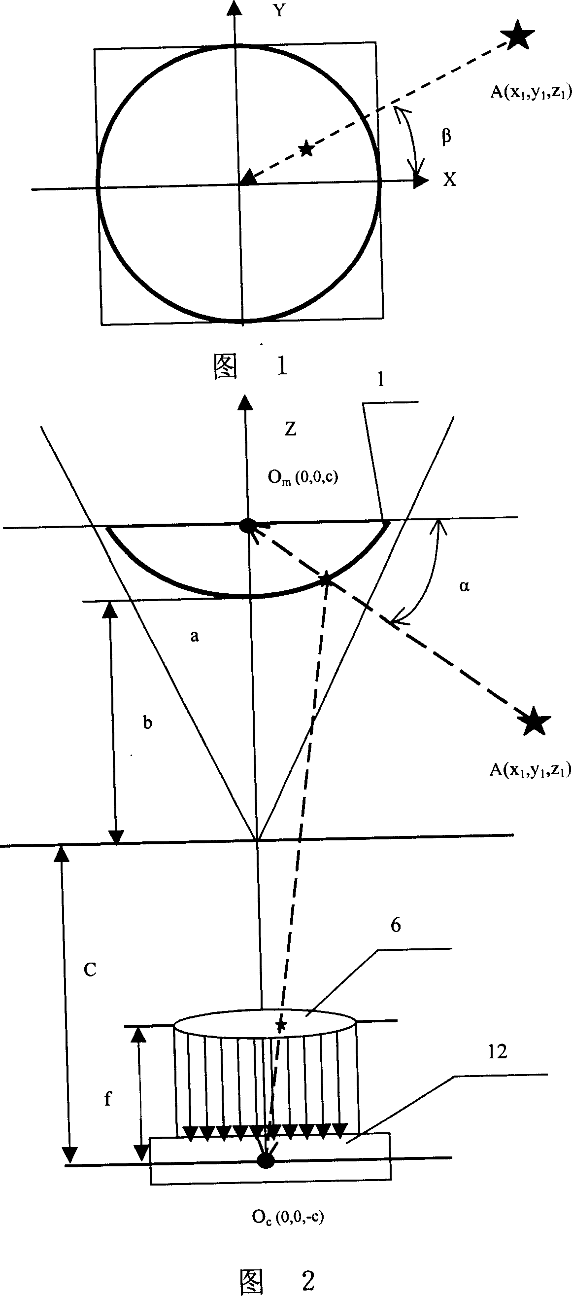
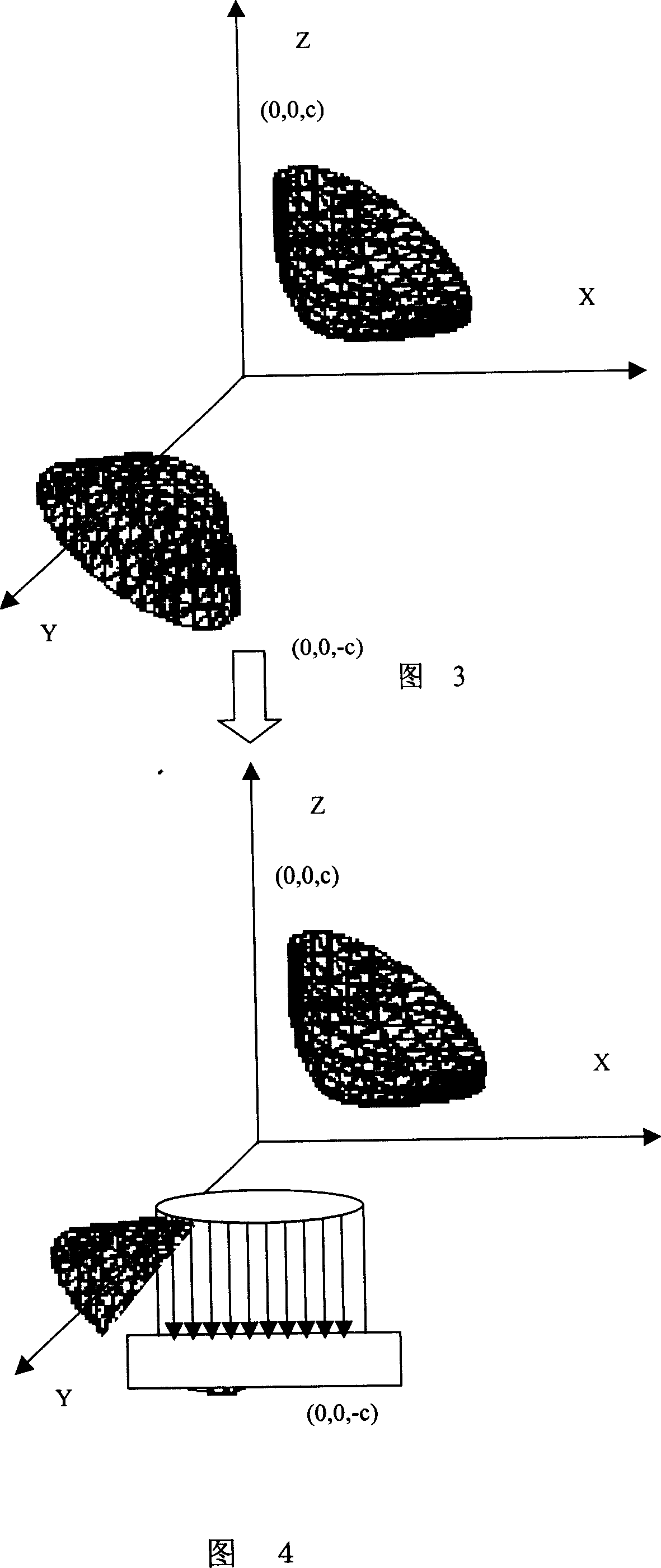
[0098] refer to Figure 12 , Figure 13, Figure 15, Figure 18 , Figure 19 , an omnidirectional vision device, including an omnidirectional camera unit, a microprocessor 15, a memory 17, and a display device 16. The omnidirectional camera unit is composed of a reflective component, a lens 5, and an imaging component 12. The reflective component It is the hyperbolic mirror 1, the CCD camera 12 is located at the virtual focus position of the hyperbolic mirror 1, the lens 5 is located between the CCD camera 12 and the hyperbolic mirror 1, and the CCD camera 12 is connected to the hyperbolic mirror 1 through the video input interface. The microprocessor 15 is communicatively connected, the display device 16 is connected with the video output interface of the microprocessor 15, and the microprocessor 15 includes an image acquisition module 24 for collecting images obtained on the CCD camera unit 12; The image storage module 25 is used to store the collected image data in the memo...
Embodiment 2
[0155] refer to Figure 12 , Figure 14 , Figure 16, Figure 18 , Figure 19 , the basic composition and working principle of the optical part and the electronic part of the present embodiment are basically the same as those of the embodiment 1, the difference is that the image expansion processing module adopts the mapping matrix expansion algorithm: the expansion processing module 29 includes: the reading coordinate information unit 30, the The data such as the center coordinates of the circular omnidirectional image calculated in the above-mentioned initialization module and the radius of the inner and outer circles of the image are read into the program to expand the calculation; the mapping matrix expansion unit 39, the circular omnidirectional calculated in the above-mentioned initialization module is read into the program. The center coordinates of the image and the radius of the inner and outer circles of the image, and the center coordinates of the circular omnidire...
Embodiment 3
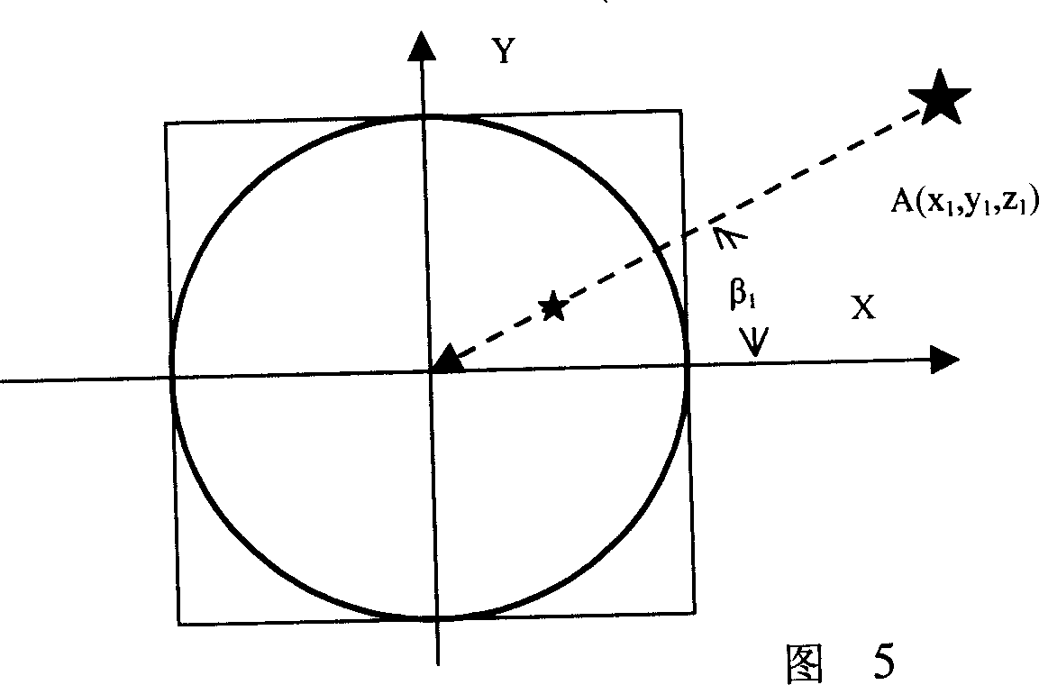
[0163] refer to Figure 12 , Figure 14 , Figure 17, Figure 18 , Figure 19 , the basic composition and basic principle of the optical part and the electronic part of this embodiment are basically the same as those of the embodiment 1, and the difference is that the image expansion processing module adopts a polar coordinate expansion algorithm: the expansion processing module 29 includes: the reading coordinate information unit 30, the The data such as the center coordinates of the circular omnidirectional image calculated in the above-mentioned initialization module and the radius of the inner and outer circles of the image are read into the program so as to expand the calculation; the polar coordinate expansion calculation unit 40 is used for the position of the center point of the omnidirectional image. And the inner diameter is r, the outer diameter is R, r is the radial length of any point on the image from the inner circle, and the azimuth angle is: β=tan -1 (y * / ...
PUM
 Abstract
Description
Claims
Application Information
 - R&D
- Intellectual Property
- Life Sciences
- Materials
- Tech Scout
- Unparalleled Data Quality
- Higher Quality Content
- 60% Fewer Hallucinations
Browse by: Latest US Patents, China's latest patents, Technical Efficacy Thesaurus, Application Domain, Technology Topic, Popular Technical Reports.
© 2025 PatSnap. All rights reserved.Legal|Privacy policy|Modern Slavery Act Transparency Statement|Sitemap|About US| Contact US: help@patsnap.com