
Device and method for digital exposure

A digital and exposure unit technology, which is applied to permanent visual display devices, visual demonstrations using printers, and visual performance of photographic printing. It can solve problems such as incompetent data flow, and light modulators that do not provide shift register functions.

Inactive Publication Date: 2012-07-25
赛康预压公司
View PDF1 Cites 0 Cited by
  • Summary
  • Abstract
  • Description
  • Claims
  • Application Information

AI Technical Summary

Problems solved by technology

[0004] However, when using the rolling method, the following problem arises: the light modulator - i.e. the LCD display or the DMD chip itself - does not provide a shift register function
The usual control of light modulators by means of a computer is not adequate for these data streams
The processing of the exact position of the exposure unit and the synchronization with the image data also requires high-resolution real-time access to the instantaneous position data, which is not possible even with a PC with a real-time operating system

Method used


Image

  • Device and method for digital exposure
  • Device and method for digital exposure

Examples


Embodiment Construction

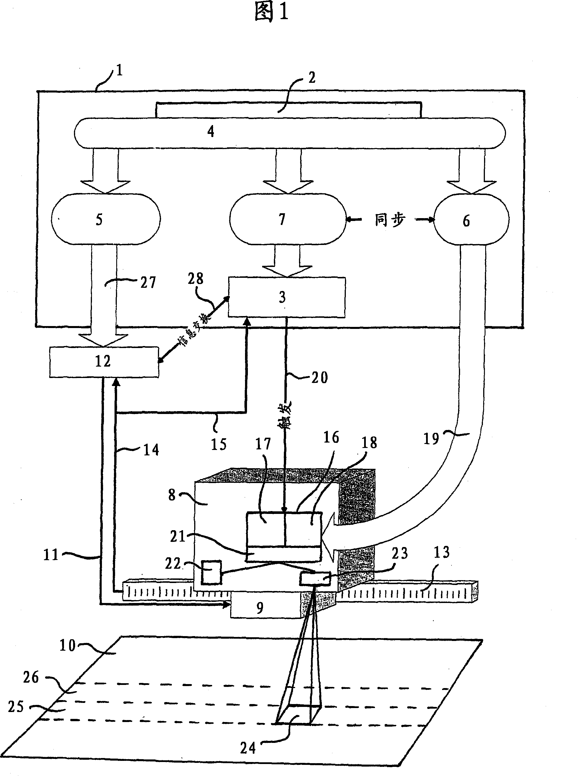
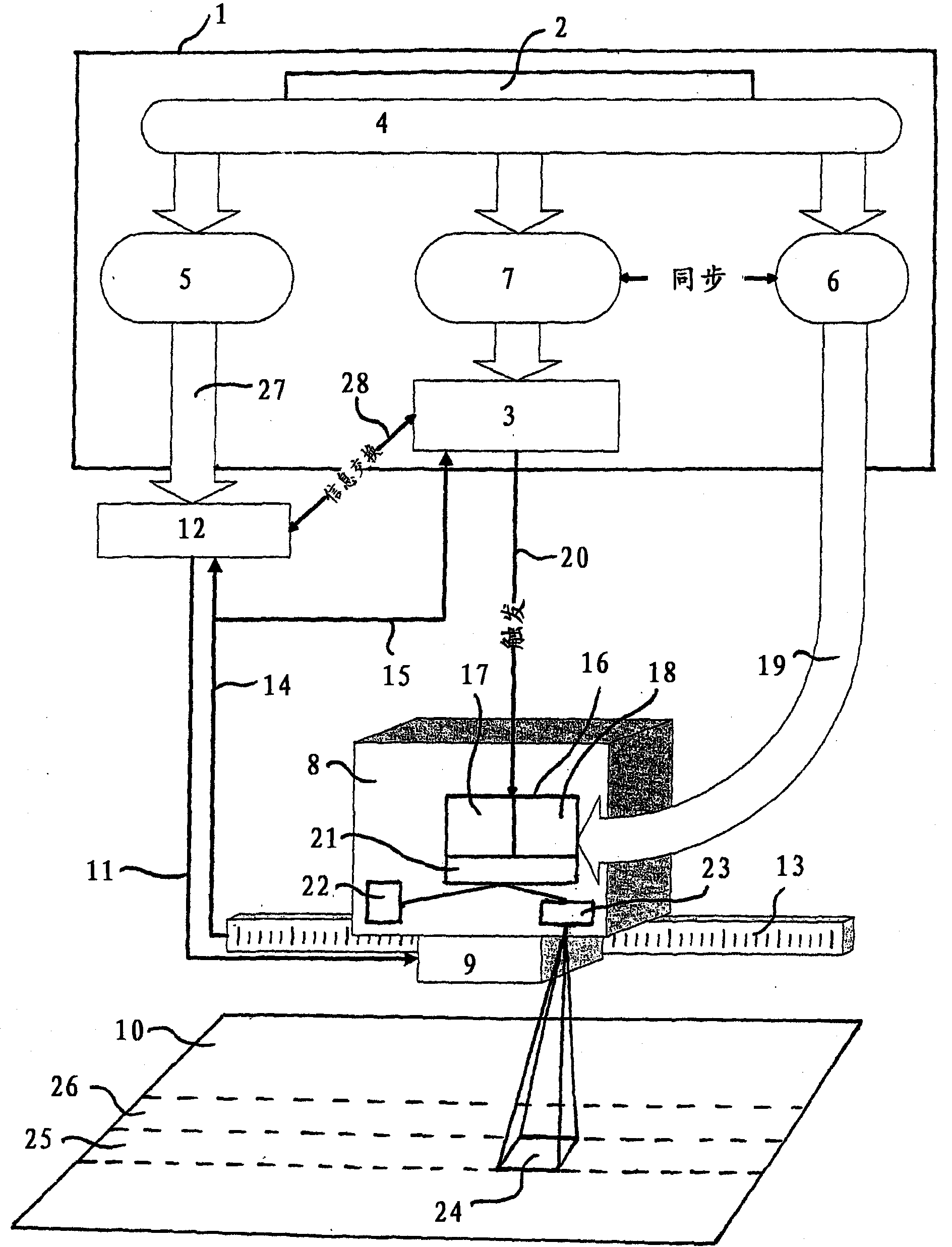
[0021] exist figure 1 , the control device 1 represented by a box can be seen. The control device 1 consists of a computer with an image memory 2 , a control program and a trigger card 3 . The control program includes exposure data manager 4, position data manager 5, image data manager 6 and scrolling device 7 representing the highest program level. Data flow is indicated by arrows.

[0022] Outside the control device 1, an exposure unit 8 is arranged, wherein the exposure unit 8 is provided by means of two servo motors - which are in figure 1 Only the servomotor 9 is shown in FIG. 2 , which is arranged displaceably in two dimensions on the surface of the printing plate 10 to be exposed. The servomotor 9 is designed as a linear motor and is connected to a motor control 12 via a control line 11 . The same applies to the other servomotor, not shown. The position sensor 13 generates position data about the corresponding position of the exposure unit 8 and sends these data vi...


PUM


Abstract

The invention relates to a device for exposing light-sensitive materials, with an electronic picture memory ( 2 ) for storing a master image, with an exposure unit which comprises a light source ( 22 ), an electronically activatable light modulator ( 21 ) for representing a part picture ( 24 ) of the master image ( 2 ), and imaging optics ( 23 ) for the projection of the part picture ( 24 ) onto the light sensitive material ( 10 ), with a drive device consisting of motors ( 9 ) and of a motor control ( 12 ), for moving the exposure unit ( 8 ) parallel to the surface of the light-sensitive material ( 10 ), with a scroll means ( 7 ) for scrolling a picture strip ( 25, 26 ) of the master image through the light modulator ( 21 ), and with a control device ( 1 ) for synchronising the drive device ( 9, 12 ) with the scroll means ( 7 ). For reducing the processing time for the exposure of the complete printing plate ( 10 ), according to the invention, it is envisaged for a rapid intermediatememory ( 16 ) for storing a strip-like region to be provided, from which the picture data for the part picture ( 24 ) to be exposed, in each case, may be transmitted onto the light modulator ( 21 ) synchronously with the movement of the exposure unit ( 8 ).

Description

technical field [0001] The invention relates to an apparatus and method for digitally exposing photosensitive materials. The device has an electronic image memory for storing the reticle; an exposure unit, which preferably includes a light source, an electrically controllable light modulator for representing a partial image of the reticle, and a projection for projecting the partial image onto a photosensitive material Optics; drive means, consisting of, for example, servo motors and motor controls, for moving the exposure unit parallel to the surface of the photosensitive material; rolling means for rolling the image tape of the plate through the light modulator; and drive means for Control device synchronized with scrolling device. Background technique [0002] Such an exposure device is disclosed, for example, in WO01 / 21413A1. Transmissive LCD displays or reflective micromirror devices - also known as DMDs or digital mirror elements - are suitable as light modulators. ...

Claims


Application Information

Patent Timeline
Patent Type & Authority Patents(China)
IPC IPC(8): G06K15/12
CPCG06K15/1252G06K15/1894
Inventor 弗莱德瑞奇·卢劳斯泰凡·艾格尔
Owner 赛康预压公司
Learn More