Phosphor film, lighting device using the same, and display device

A lighting device, phosphor technology, applied in the direction of lighting device, lighting device parts, lighting and heating equipment, etc.

Inactive Publication Date: 2006-12-20
DAWNCREST IP LLC
View PDF3 Cites 39 Cited by
  • Summary
  • Abstract
  • Description
  • Claims
  • Application Information

AI Technical Summary

Problems solved by technology

Therefore, effective color mixing will no longer be possible after a long period of time

Method used


Image

  • Phosphor film, lighting device using the same, and display device
  • Phosphor film, lighting device using the same, and display device
  • Phosphor film, lighting device using the same, and display device

Examples


no. 1 example

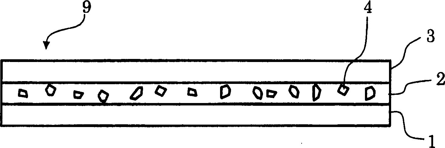
[0068] The following will be combined with figure 1 The structure of the phosphor thin film according to the first embodiment of the present invention will be described. As shown in the figure, in a phosphor film 9 , phosphor particles 4 are mixed in an adhesive 2 and applied on a translucent film 1 . The layer comprising binder 2 and phosphor particles 4 is called phosphor layer. The waterproof layer 3 covers the phosphor layer to protect the phosphor particles from moisture.

[0069] The material of phosphor microparticles 4 is appropriately selected according to the excitation light wavelength to be used and the target emission wavelength. For example, when light emitted from a white LED generally used in a lighting device of a liquid crystal display device is used as excitation light, the light emitted from the lighting device is called pseudo white light. Figure 7 The wavelength luminance characteristics of pseudo-white light are shown in . As shown in the figure, t...

Embodiment 2

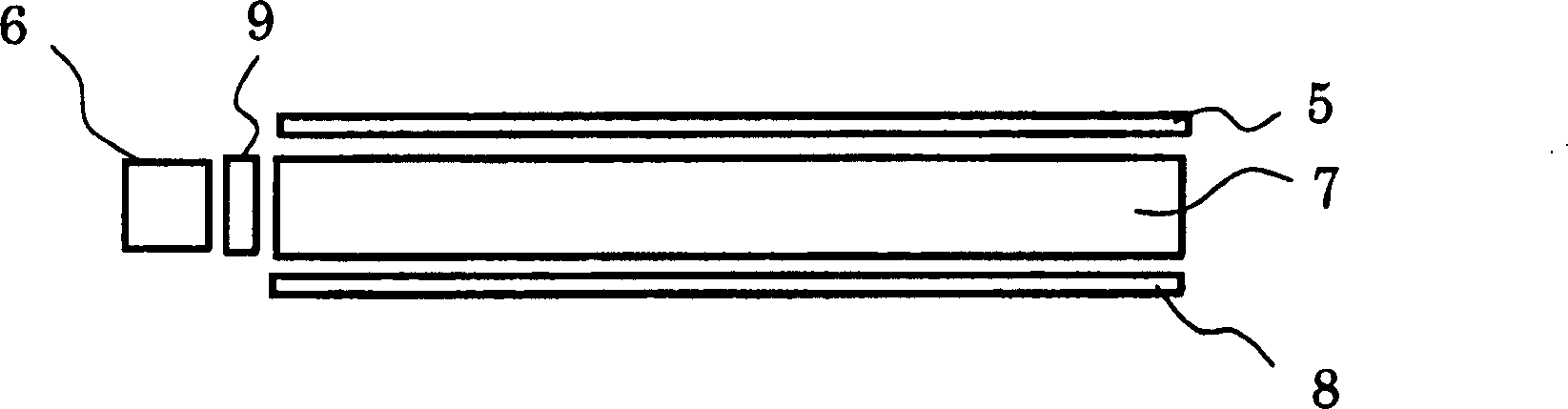
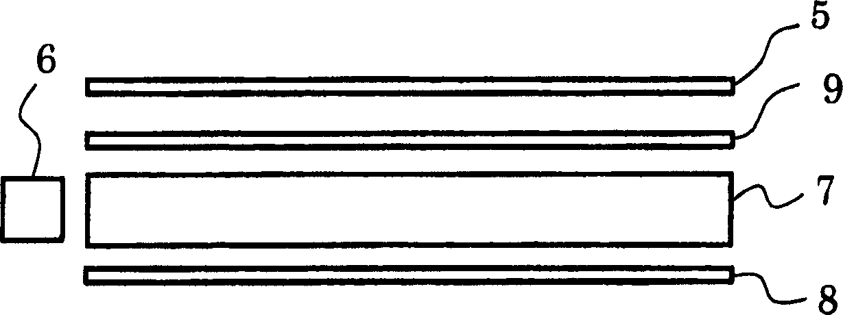
[0072] figure 2 The structure of the lighting device according to the second embodiment of the present invention is shown in . The lighting device according to this embodiment is a so-called edge-light type lighting device in which the light source is on the side of the light guide. As shown in the figure, a phosphor film 9 is placed between the light source 6 and the light guide 7 . Light emitted from the light source 6 passes through the phosphor film 9 to be converted into light of a desired wavelength. The light guide 7 guides the converted light to emerge from the emitting surface of the lighting device by the reflective plate 8 and the prismatic sheet 5 . As in the first embodiment, in the phosphor film 9, a phosphor layer is formed by mixing phosphor fine particles in a binder on a translucent film. The translucent film must be located somewhere between the light source and the emitting surface of the lighting device. image 3 A structure with a phosphor film 9 dis...

no. 3 example

[0074] Figure 4 The structure of the display device according to the third embodiment of the present invention is shown in . In this example, figure 2 The edge-lit type lighting device shown in is used as a backlight for a display device. A liquid crystal display element is used as a display element. As shown in the figure, a phosphor film 9 is placed between the light source 6 and the light guide 7 . Light emitted from the light source 6 passes through the phosphor film 9 to be converted into light having a desired wavelength. The converted light is guided into the direction of the liquid crystal display element 10 by the light guide 7 , the reflector 8 and the prism sheet 5 ; and the converted light is sampled by the color filter in the liquid crystal display element 10 to emit light of display color.

[0075] Figure 6 The transmission characteristics of the color filter of the liquid crystal display element are shown in . Among the color filters, the transmission c...


PUM

PropertyMeasurementUnit
thicknessaaaaaaaaaa
thicknessaaaaaaaaaa
thicknessaaaaaaaaaa

Abstract

The invention realizes a phosphor film that has a fluorescent characteristic excellent in resistance to humidity and provides, using the phosphor film, a liquid crystal display device that is excellent in resistance to humidity and has satisfactory calorimetric property and color mixture property. Phosphor particles that are excited by incident light and emit light having a wavelength different from the incident light are mixed in a binder. The binder mixed with the phosphor particles is sandwiched between a translucent film and a non-permeable layer as a phosphor layer to form a phosphor film. This phosphor film is provided at least in one place among a place between a light source and a light guide of a lighting device, a place on a light irradiation surface of the light guide, and a place between the light guide and a reflection plate. Moreover, the phosphor particles have a characteristic that a wavelength absorbed by a color filter of a display element is set as an excitation wavelength and a luminescent wavelength is in a region transmitted by the color filter. With this phosphor film, it is possible to realize a display device that has extremely high luminance efficiency and color reproducibility.

Description

technical field [0001] The present invention relates to a lighting device for lighting a display element used in a portable information device, a cellular phone, etc., and a display device using the lighting device, and more particularly, to a phosphor film used in the lighting device. Background technique [0002] In recent years, liquid crystal display devices that obtain high-definition color images with small power consumption are employed as displays in cellular phones, mobile computers, and the like. Since the liquid crystal display device is a non-self-luminous display device that does not emit light, it needs an illuminating device. Superluminescent white light-emitting diodes are often used as light sources in lighting devices. [0003] In particular, reflective type liquid crystal display devices with large and bright openings or double-side viewable liquid crystal display devices will be used in portable phones. The device can display image information on its fr...

Claims


Application Information

Patent Timeline
Patent Type & Authority Applications(China)
IPC IPC(8): F21V8/00F21V9/08H01L33/00G02F1/1335F21S2/00F21Y101/02G02F1/13357
Inventor 栗原慎出岛范宏
Owner DAWNCREST IP LLC
Why Eureka
Try Eureka