Light guide plate and backlight module assembly

A technology of backlight module and light guide plate, which is applied in the direction of light guide, optics, optical components, etc., can solve the problems of unfavorable light energy utilization rate, reflection and scattering loss, etc., and achieve the goal of improving light energy utilization rate and light energy utilization rate Effect

Active Publication Date: 2006-12-20
TSINGHUA UNIV +1
View PDF0 Cites 7 Cited by
  • Summary
  • Abstract
  • Description
  • Claims
  • Application Information

AI Technical Summary

Problems solved by technology

[0007] However, since the linearly polarized light S reflected by the reflective polarization beam splitter 47 in the backlight module 40 must exit the light guide plate 42, it can be converted into linearly polarized light P1 by the 1 / 4 wave plate 46, and the 1 / 4 wave Reflection and scattering loss will occur at the interface of sheet 46 and light guide plate 42, which is still not conducive to the improvement of light energy utilization efficiency

Method used


Image

  • Light guide plate and backlight module assembly
  • Light guide plate and backlight module assembly
  • Light guide plate and backlight module assembly

Examples


Embodiment Construction

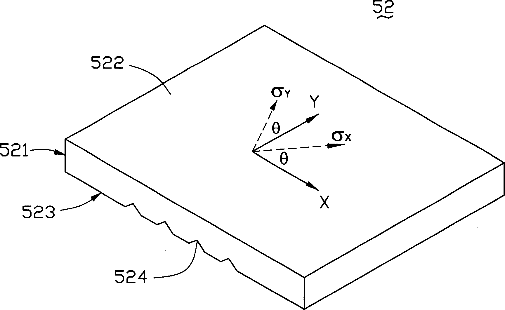
[0025] Such as image 3 As shown in FIG. 1 , is a perspective view of the light guide plate according to the first embodiment of the present invention. The light guide plate 52 is flat and includes a light incident surface 521 , a light exit surface 522 perpendicular to the light incident surface 521 , and a bottom surface 523 opposite to the light exit surface 522 . The bottom surface 523 of the light guide plate 52 is provided with microstructures 524 . In this embodiment, the light guide plate 52 is made of polycarbonate material, the microstructure 524 is a V-shaped groove, and the light emitting surface 522 is a plane.

[0026] The light guide plate 52 is a stress birefringent light guide plate made by applying stress or strain by utilizing the photoelastic effect. Such as image 3 As shown, first define the direction perpendicular to the light incident surface 521 of the light guide plate 52 as the X axis, and the direction perpendicular to the X axis and parallel to ...


PUM


Abstract

The invention discloses a light conductive board and aphototropism module, which comprises the following parts: light-in plane, light-out plane corresponding to light-in plane vertically and floor corresponding to light-out plane, wherein the light conductive board is stress double-reflecting conductive board with one direction of separation angle of main stress between 0 and 90 deg; the secondary wavelength grid structure is set on the light-out plane of light conductive board.

Description

【Technical field】 [0001] The invention relates to a light guide plate and a backlight module with high utilization rate of light energy. 【Background technique】 [0002] Since the liquid crystal in the liquid crystal display panel itself does not have light-emitting characteristics, in order to achieve the display effect, it is necessary to provide a backlight module for the liquid crystal display panel. light source. [0003] A kind of prior art backlight module such as figure 1 As shown, the backlight module 20 and the liquid crystal display panel 10 form a liquid crystal display device 100 . The backlight module 20 includes a light source 21 , a light guide plate 22 , a reflection sheet 23 , a diffusion sheet 24 and a prism sheet 25 . The upper and lower surfaces of the liquid crystal display panel 10 are respectively provided with an upper polarizer 11 and a lower polarizer 12 . The light source 21 in the backlight module 20 is disposed opposite to the side of the lig...

Claims


Application Information

Patent Timeline
Patent Type & Authority Applications(China)
IPC IPC(8): G02F1/1335G02B5/02
CPCG02B6/0038G02B6/0056G02B6/0036
Inventor 杨兴朋严瑛白金国藩
Owner TSINGHUA UNIV
Why Eureka
Try Eureka