Cathode ray tube

A technology for cathode ray tubes and tube shells, applied in the direction of cathode ray/electron beam tube shells/containers, cold cathode manufacturing, electrode system manufacturing, etc., which can solve problems such as weight increase, panel 3 price increase, long time, etc. Achieve the effect of reducing weight, reducing material cost and reducing heat supply

Inactive Publication Date: 2006-12-20
MATSUSHITA TOSHIBA PICTURE DIS
View PDF2 Cites 0 Cited by
  • Summary
  • Abstract
  • Description
  • Claims
  • Application Information

AI Technical Summary

Problems solved by technology

That is, since the weight of the panel 3 increases, the price of the panel 3 becomes high
In addition, in the sealing process, it takes a very long time to uniformly heat up the temperature distribution of the panel 3

Method used


Image

  • Cathode ray tube
  • Cathode ray tube
  • Cathode ray tube

Examples


Embodiment Construction

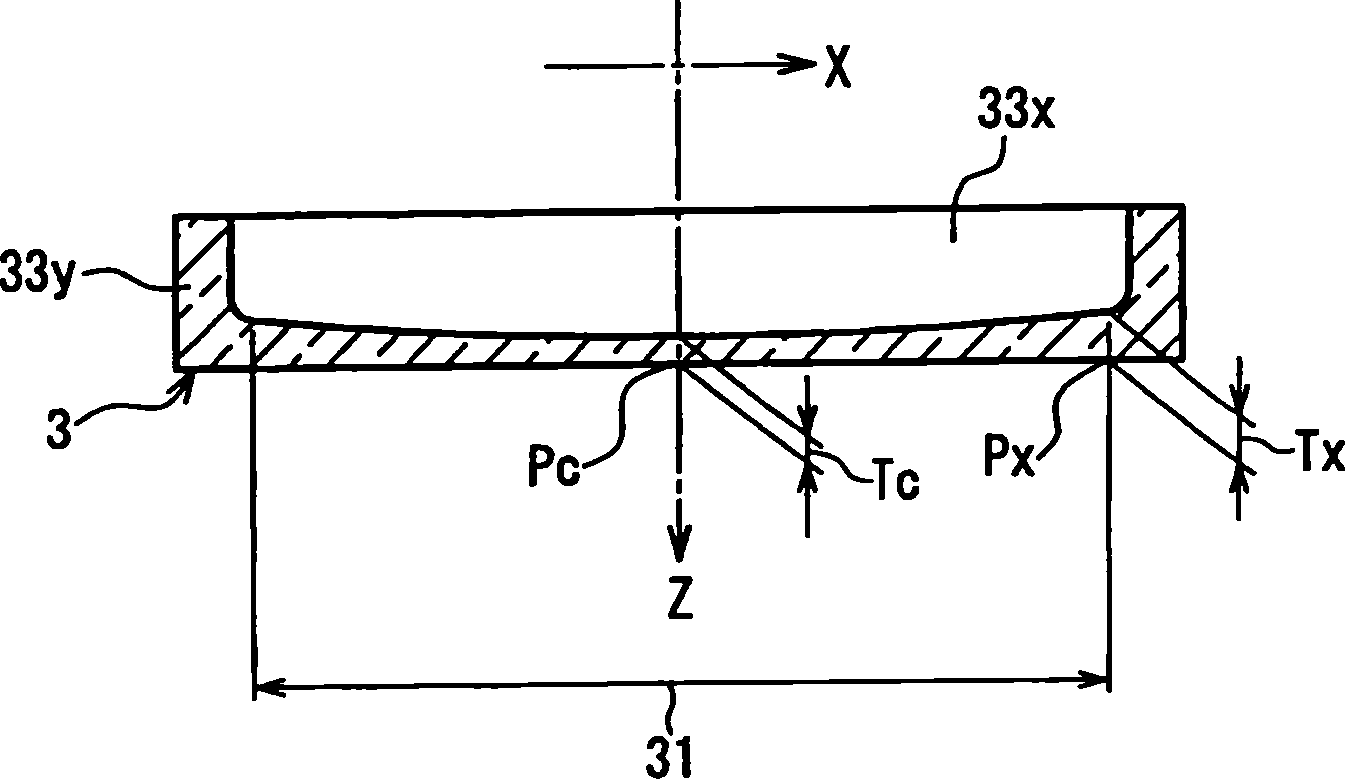
[0027] The above-mentioned cathode ray tube of the present invention further includes a metal tape mounted on the outer peripheral surface of the skirt portion of the panel, and a resin sheet pasted so as to cover at least the outside of the effective portion, preferably satisfying the following formula (3):

[0028] 0.012≤Tc / D≤0.016…………………………(3)

[0029] Therefore, even if the casing of the cathode ray tube is crushed, the glass sheet of the panel can be prevented from splashing to the front of the panel. As a result, it can fully meet the Electrical Appliances and Materials Regulations, UL (Underwriters Laboratories Inc. Underwriters Laboratories) standards, CSA ( Canadian Standards Association Canadian Standards Association) standards and other strict safety standards. In addition, there is no need to increase the thickness of the panels in order to meet these safety standards. Therefore, not only sufficient safety can be ensured, but also the weight and cost of the panel ...


PUM


Abstract

The invention provides color cathode tube.When the thickness of the panel at an X axis end of the useful portion is expressed by Tx (mm), the thickness thereof at a Y axis end is expressed by Ty (mm), the thickness thereof at the center is expressed by Tc (mm) and an outer dimension of the panel along the diagonal axis direction is expressed by D (mm), 0.8<=(100xTC / D)2x(Tx / Ty)<=2.2 and 0.012<=Tc / D<=0.019 are satisfied. Accordingly, the stress generated in a short side and that generated in a long side in a sealing portion in an exhausting process are substantially equalized. As a result, cracking of the panel can be reduced in the exhausting process even when the panel is made thinner. Therefore, it is possible to provide a cathode ray tube that is easy to manufacture and has a lighter and less expensive panel.

Description

technical field [0001] This invention relates to cathode ray tubes. Background technique [0002] As shown in FIG. 9, a cathode ray tube 1 used in a television receiver or the like includes a glass panel 3 on which a phosphor 2 or the like is applied and a glass panel 3 on which a conductive film 4 or the like is formed, sealed with frit glass 8. The shell 10 formed by making a funnel (funnel) 5. An electron beam emitted from an electron gun 6 arranged in the neck portion 5 a of the funnel 5 collides with the phosphor 2 to emit light, thereby displaying an image. [0003] As a process for manufacturing such a cathode ray tube 1, there is a sealing process in which the panel 3 and the funnel 5 are sealed in a furnace at about 450°C in order to seal them with frit glass 8, or a sealing process in which the inside of the cathode ray tube 1 is vacuumed. Exhaust process in the furnace at about 350°C. Especially in the evacuation process, the package 10 is subjected to thermal ...

Claims


Application Information

Patent Timeline
Patent Type & Authority Applications(China)
IPC IPC(8): H01J29/86
CPCH01J9/244H01J29/87H01J29/86
Inventor 川崎正树山下浩之山内真英井口秀郎河野正治川本明美
Owner MATSUSHITA TOSHIBA PICTURE DIS
Why Eureka
Try Eureka