
Roll holding unit

A technology of holding device and roller, applied in the direction of hand-held tools, manufacturing tools, etc., can solve the problems of heavy products and complicated production, and achieve the effects of low material, simple and convenient replacement, and low production cost.

Inactive Publication Date: 2006-12-20
VON ARX AG
View PDF2 Cites 0 Cited by
  • Summary
  • Abstract
  • Description
  • Claims
  • Application Information

AI Technical Summary

Problems solved by technology

This makes the product heavier and complicates production

Method used


Image

  • Roll holding unit
  • Roll holding unit
  • Roll holding unit

Examples


Embodiment Construction

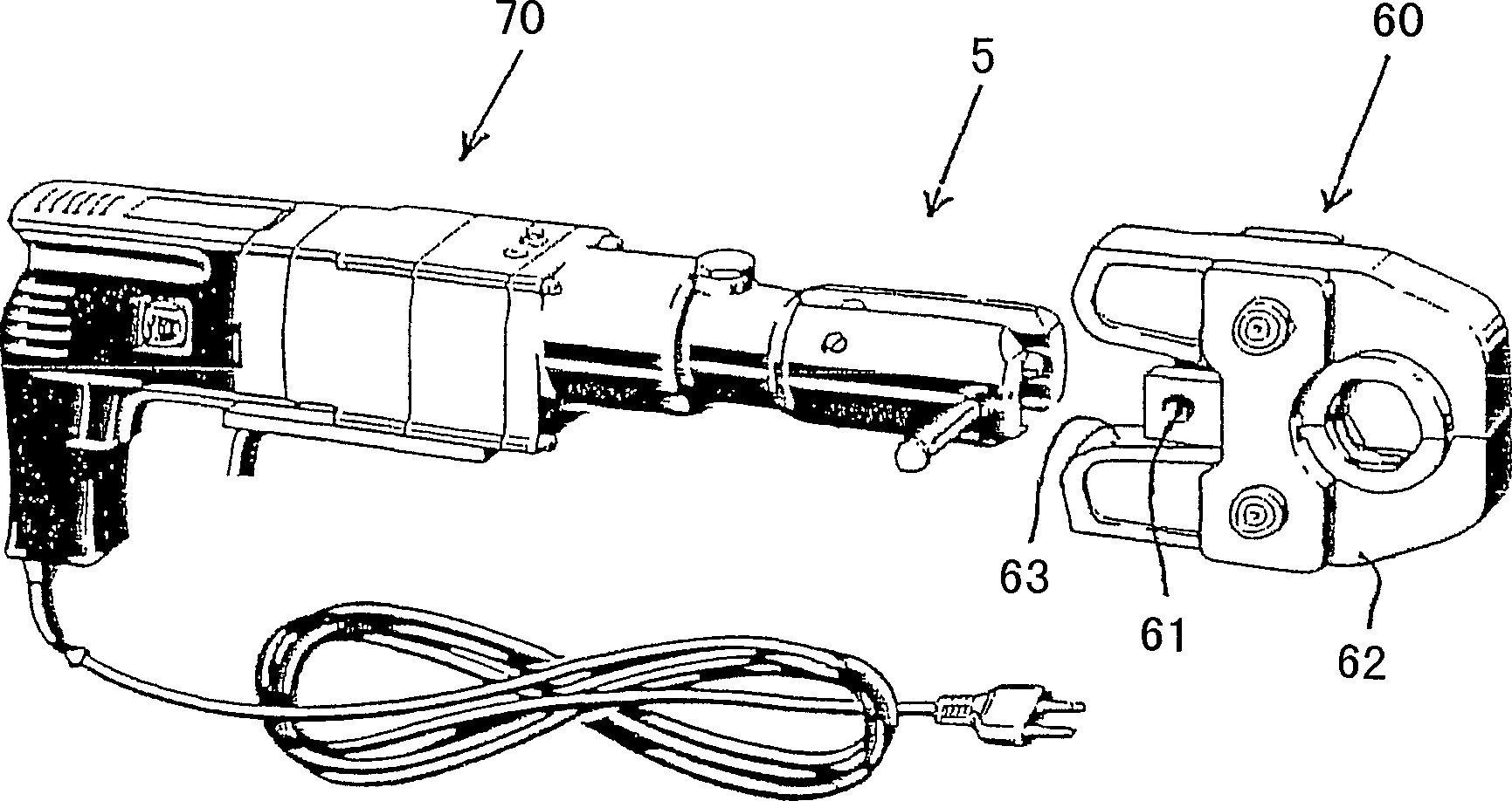
[0028] figure 1 A prior art extrusion tool is shown. The pressing tool comprises: a drive unit 70 ; a piston-cylinder assembly 5 with a fork-shaped receiver 55 ; and existing clamps 60 . Clamp 60 is fastened to a T-shaped mount connected to fork receiver 55 by retaining bolt 54 and retaining bolt receiver 61 . A roller holder with two rollers is placed in the fork receiver 55 . Fork receiver 55 is part of a piston-cylinder assembly. Once the piston rod is pushed forward, the roller rolls on the jaws 62 of the clamp 60 . In this way, since the rear portion of the jaws 62 is squeezed and separated by the action of the rollers, the clamps 60 are squeezed together, thus completing the clamping operation.

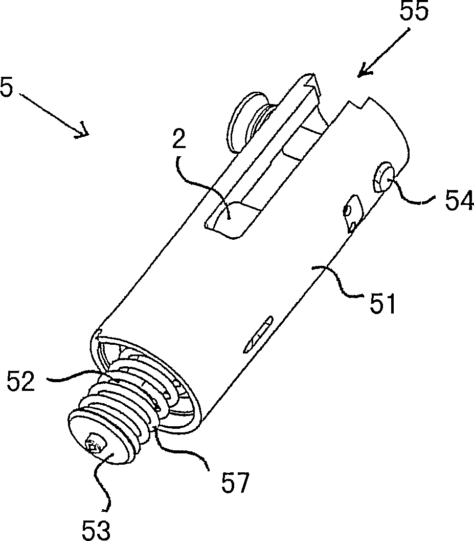
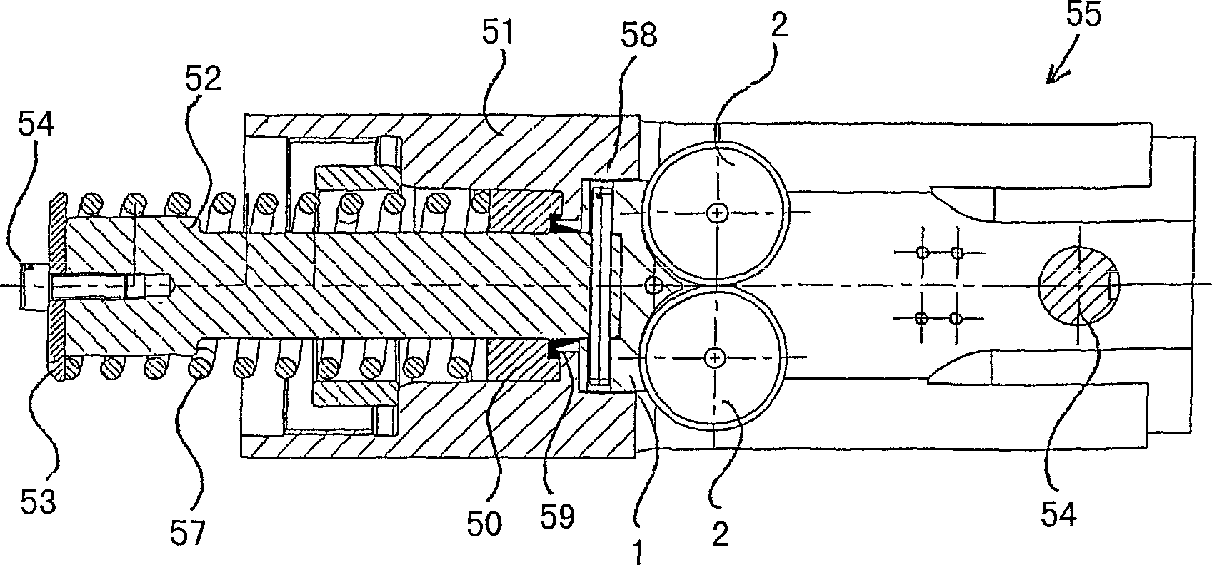
[0029] The piston-cylinder assembly 5 constitutes the connecting part of the driving device 70 and the clamp 60 . Such as figure 2 As shown, the piston-cylinder assembly 5 includes a cylinder cover 51 having a through hole for receiving a retaining bolt 54 for fastening t...


PUM


Abstract

The invention relates to a roll holding unit for a press tool. Said roll holding unit comprises a bearing block (1) and at least one lateral fixing metal plate (3) which is arranged on the block and securely fixes two rolls (2) in a rotatable manner. The bearing block (1) for each roll (2, 2') is provided with a plain bearing surface (11, 12), the form of said surface corresponding to the rolling surface and thus the outer diameter of the roll (2, 2').

Description

technical field [0001] The invention relates to a roller holding device for a pressing tool according to the preambles of the independent claims. Background technique [0002] From German patent DE-19631019 it is known: a extrusion tool comprising extrusion jaws for connecting a pipe to a press fitting. The squeeze pliers comprise two pivoting arms each pivotally connected between two identical "T" shaped bearing plates by a bolt. The piston-cylinder assembly is articulated to a roller holder that includes two rollers therein. One end of the pivot arm is provided with a rolling surface for supporting on the extrusion cylinder of the extrusion tool. The other opposite end of the pivot arm is designed as jaws with pressing surfaces facing each other. A plurality of bolt connection devices are arranged on the bearing plate at certain intervals. Receptacles for connecting bolts for connecting the extrusion device are arranged in the region of the free end of the T-shaped car...

Claims


Application Information

Patent Timeline
IPC IPC(8): B25B27/14B25B27/10
CPCB25B27/10Y10T29/5367
Inventor 勒内·阿默赫德
Owner VON ARX AG
Learn More