Vertical member for a vehicle restraint system

Active Publication Date: 2021-08-12
DELTA BLOC INT GMBH
View PDF0 Cites 0 Cited by
  • Summary
  • Abstract
  • Description
  • Claims
  • Application Information

AI Technical Summary

Benefits of technology

[0010]It is therefore the object of the invention to provide a vertical member of the type mentioned at the beginning, with which the disadvantages mentioned can be avoided, with which the resistance of a guard rai

Problems solved by technology

The disadvantages of this are the high material costs and the associated increased material costs as well as significant disadvantages in the fastening of the vertical members in the ground, since a high

Method used


Image

  • Vertical member for a vehicle restraint system
  • Vertical member for a vehicle restraint system

Examples


Example

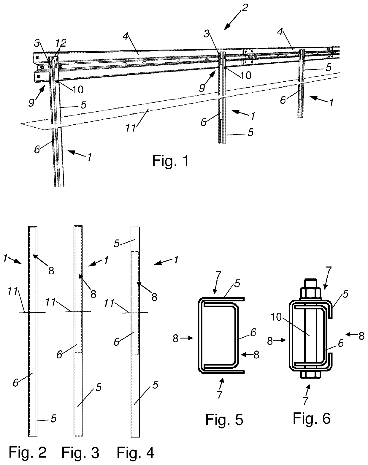
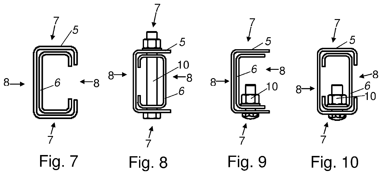
[0026]FIGS. 1 to 10 show at least parts of preferred embodiments of a vertical member 1 for a vehicle restraint system 2, wherein the vertical member 1 has at least one fastening device 3 for fastening a guard rail 4 of the vehicle restraint system 2.

[0027]The vertical member 1 is provided to be fixed in a substrate 11, in particular to be rammed or driven into a floor, and serves to hold or support a guard rail 4. A vehicle restraint system 2 generally has a number of spaced-apart vertical members 1 and one or more guard rails 4 and spatially delimits roadways in order to reduce or prevent serious accidents. In order to fasten at least one guard rail 4 to a vertical member 1, the vertical member 1 has at least one fastening device 3, in particular a fastening opening 12, for accommodating at least one screw or threaded bolt. The screw or the threaded bolt is guided and screwed through the guard rail 4 and through the at least one fastening opening 12 of the vertical member 1 in ord...


PUM


Abstract

Disclosed is a vertical member for a vehicle restraint system, said vertical member being intended for attaching a guard rail of the vehicle restraint system. The vertical member includes a profiled support and a reinforcing support within the profiled support, and the longitudinal axis of the reinforcing support runs substantially parallel to the longitudinal axis of the profiled support.

Description

CROSS-REFERENCE TO RELATED APPLICATIONS[0001]The present application is a national phase application of PCT Application No. PCT / EP2019 / 069695, filed Jul. 22, 2019, entitled “VERTICAL MEMBER FOR A VEHICLE RESTRAINT SYSTEM”, which claims the benefit of Austrian Patent Application No. A 50645 / 2018, filed Jul. 24, 2018, each of which is incorporated by reference in its entirety.BACKGROUND OF THE INVENTION1. Field of the Invention[0002]The invention relates to a vertical member for a vehicle restraint system.2. Description of the Related Art[0003]Conventional vehicle restraint systems typically feature multiple vertical members driven into the ground at constant intervals adjacent to the roadway, to which guard rails, usually made of steel, are attached. In a crash event, particularly a vehicle impact, the guard rail deforms and supports itself against the vertical members to which it is connected, which in turn deforms the vertical members, beginning in the ground, along much of their l...

Claims


Application Information

Patent Timeline
IPC IPC(8): E01F15/04
CPCE01F15/0469E01F15/0476E01F15/0423E01F15/0461
Inventor EDL, THOMASLEHMANN, STEFFEN
Owner DELTA BLOC INT GMBH
Why Eureka
Try Eureka