Solid state light engine optical system

An optical system and solid-state light source technology, applied in optics, optical components, instruments, etc., can solve problems such as complexity, short bulb life, and blur

Inactive Publication Date: 2006-12-20
CHROMNOMOTION IMAGING APPL
View PDF1 Cites 4 Cited by
  • Summary
  • Abstract
  • Description
  • Claims
  • Application Information

AI Technical Summary

Problems solved by technology

[0005] However, the disadvantages of current technology projectors are that they may be heavy, complex, or blurry; may include a large

Method used


Image

  • Solid state light engine optical system
  • Solid state light engine optical system
  • Solid state light engine optical system

Examples


Embodiment Construction

[0027] Detailed description will be made, but it should be understood that the embodiments disclosed herein are merely examples of the invention, which can be embodied in various forms. Therefore, specific structural and functional details disclosed herein are not to be interpreted as limiting the invention, but merely as a basis for the claims and as representative representations for teaching one skilled in the art to variously employ the present invention in any suitably specific structure. sexual basis.

[0028] Referring now to the accompanying drawings in detail ( Figure 1-8 ) as indicated in the disclosure.

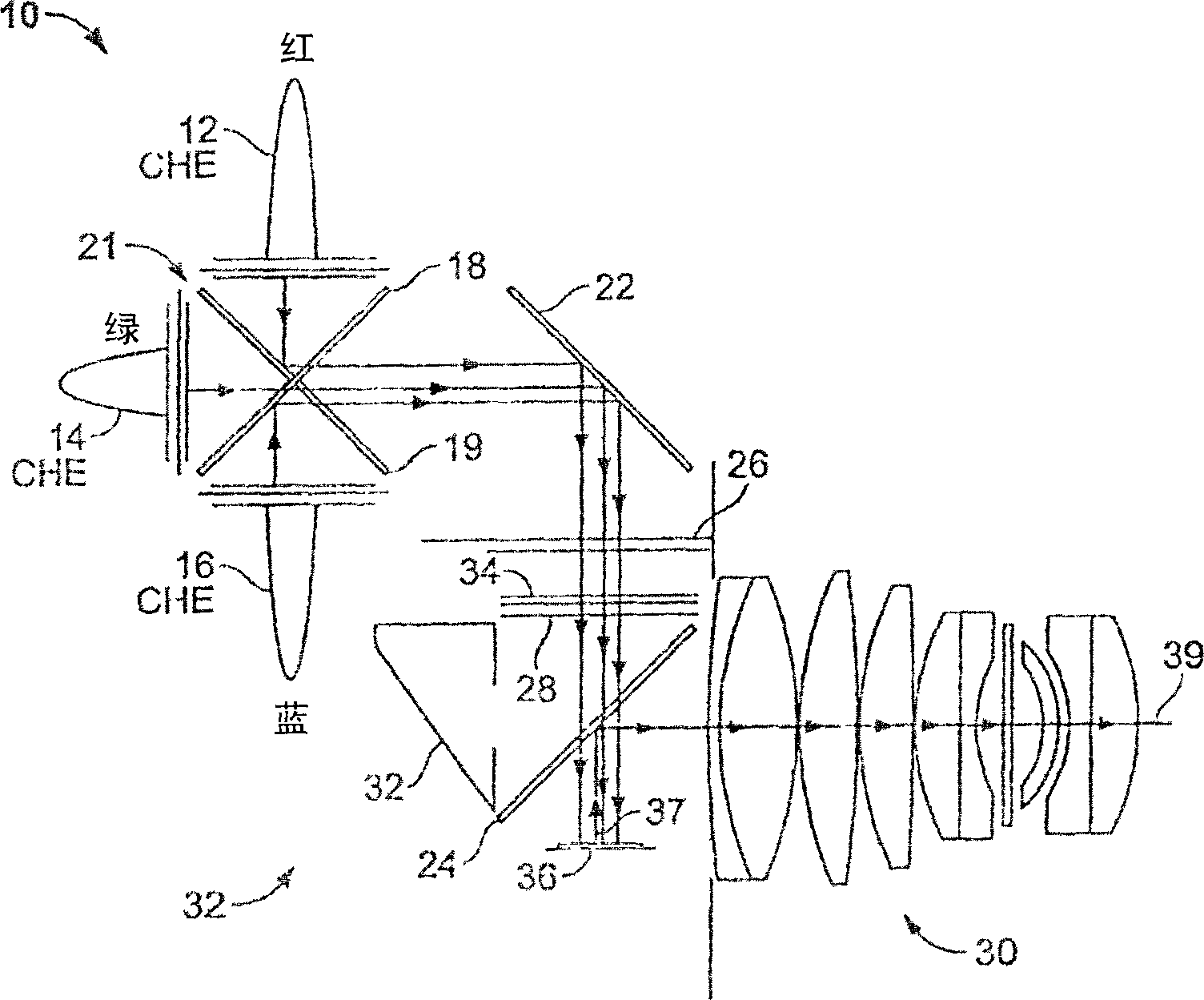
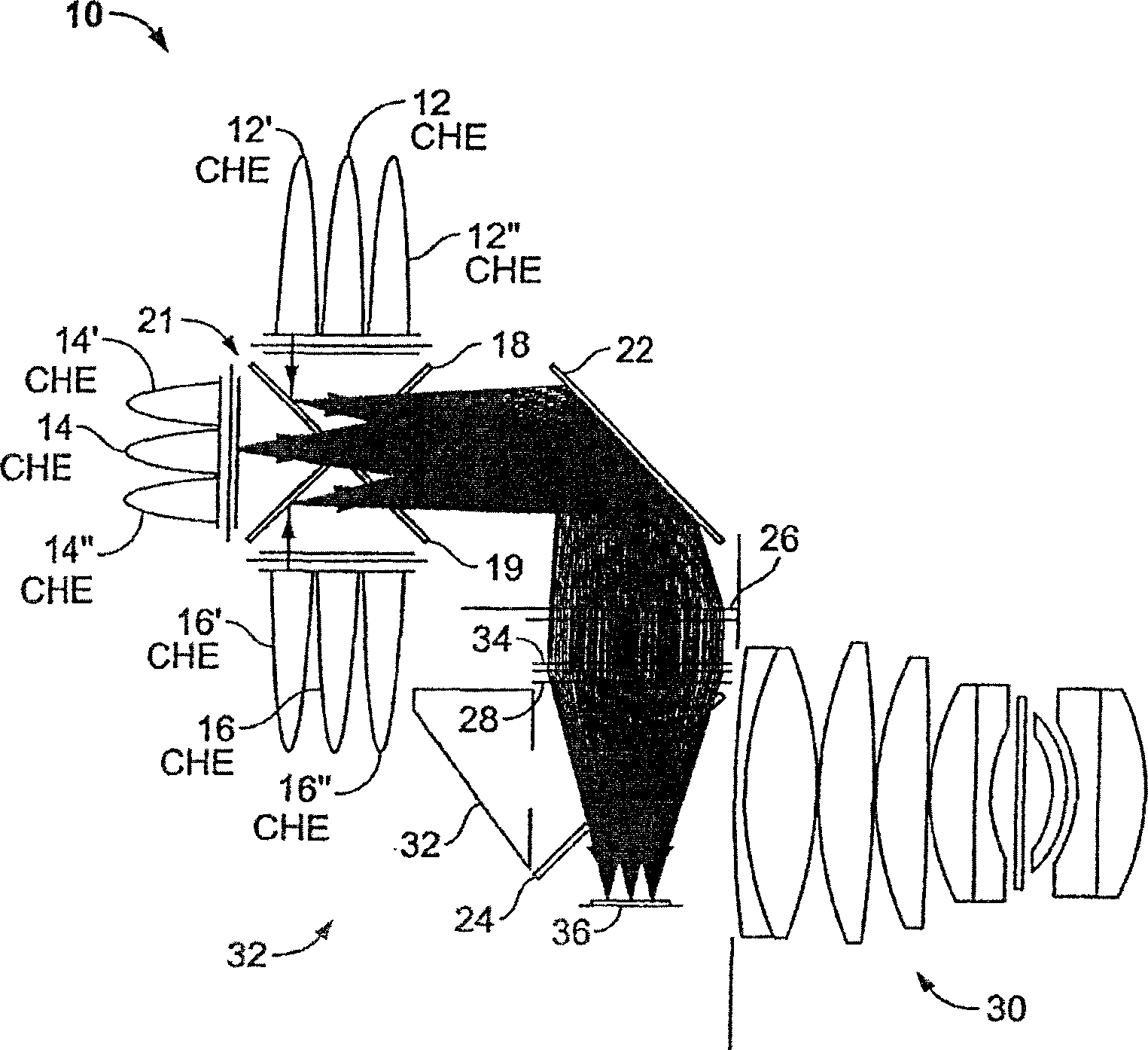
[0029] Such as figure 1 Optical system 10 is shown as a solid state projector comprised of illumination subsystem 32 and projection subsystem 30 . Illumination subsystem 32 illuminates at least one microdisplay 36 with light from a plurality of red 12, green 14, and blue 16 light emitting diodes (LEDs) arranged in separate color groups. Projection subsystem 30...


PUM


Abstract

An optical system for use in projection based displays includes a plurality of solid state light sources associated with a plurality of total internal reflection based compound hyperbolic emitters (CHE), a graduated dichroic filter based device for homogenizing light output from the plurality of solid state light sources, a ferroelectric liquid crystal on silicon device for illumination with light output from the array of light sources, and a polarization diffuser for homogenization of light at the ferroelectric liquid crystal on silicon device. The polarization diffuser is positioned at a point in space, in the optical system, where the size of a beam of light transmitted from the graduated dichroic filter device is at a maximum.

Description

[0001] Cross References to Related Applications [0002] The contents of this application are related to US Provisional Application No. 60 / 465732 (filed April 24, 2003), entitled "Personal Theater Optical System," which is incorporated herein by reference in its entirety. technical field [0003] This invention relates to light and image projectors, and more particularly to lighting devices for projection displays. technical background [0004] Current technology discloses various light sources and image projectors for viewing video and images. The simplest light projectors include flashlights, and more complex devices include image projectors with incandescent light sources, as described in US Patent No. 6,227,669. [0005] However, the disadvantages of projectors in current technology are that they may be heavy, complex, or blurry; may include a large number of expensive parts; be bulky; generate excessive heat; require cooling fans; generate excessive noise; or have shor...

Claims


Application Information

Patent Timeline
IPC IPC(8): G02B27/00G02B27/14H01L33/00
Inventor 凯文·J·加西亚米切尔·C·鲁达蒂尔曼·施图林格
Owner CHROMNOMOTION IMAGING APPL
Why Eureka
Try Eureka