Supercharge Your Innovation With Domain-Expert AI Agents!

Negative pressure type booster device

一种助力器、负压式的技术,应用在负压式助力器装置领域,能够解决节流噪音泄漏等问题,达到平稳操作、结构紧凑、抑制噪音的效果

Inactive Publication Date: 2006-12-27
ADVICS CO LTD
View PDF2 Cites 2 Cited by
  • Summary
  • Abstract
  • Description
  • Claims
  • Application Information

AI Technical Summary

Problems solved by technology

However, since there is no muffler arranged in the additional air passage for the rapid entry of atmospheric air, the throttling noise is likely to Leakage
[0007] Furthermore, in the device of the aforementioned patent, since the relative displacement between the sleeve and the valve member slightly increases after opening the valve member causing a sharp increase in output power, the responsiveness exhibits two modes of operation, including the normal operation state and the response There is a problem that the responsiveness characteristic of the booster that changes according to the depression state of the brake pedal cannot be obtained.

Method used


Image

  • Negative pressure type booster device
  • Negative pressure type booster device
  • Negative pressure type booster device

Examples


Embodiment Construction

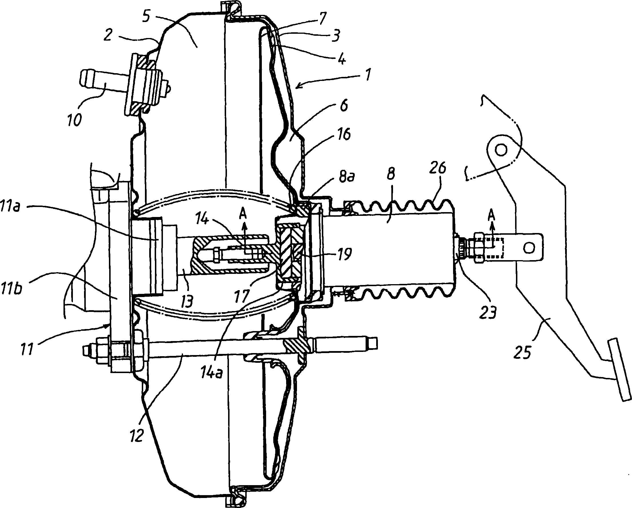
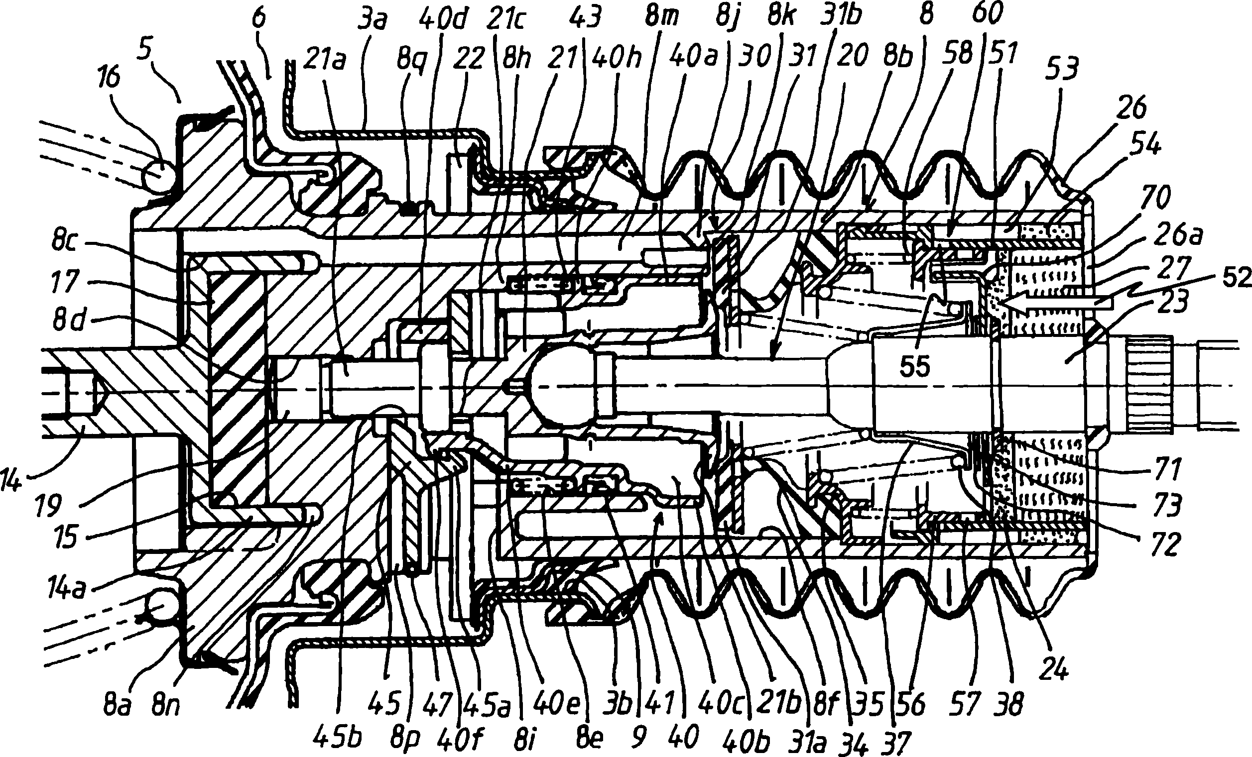
[0038] Hereinafter, a negative pressure booster device according to an embodiment of the present invention will be described with reference to the accompanying drawings. now refer to figure 1 , The booster housing 1 is composed of a front housing 2 and a rear housing 3 . Between the two housings 2 and 3, a flexible diaphragm 4 serving as a partition member is airtightly fixed at its peripheral rim portion, and divides the interior of the booster housing 1 into a constant pressure chamber 5 and a variable pressure chamber. pressure chamber6. The disc plate 7 is laminated on the diaphragm 4 inside the constant pressure chamber 5 . The valve piston 8 is airtightly fixed on the diaphragm 4 and the plate 7 at the outer surface of its base 8 a with the front end surface of the base 8 a exposed to the constant pressure chamber 5 . The negative pressure guide conduit 10 is attached on the front housing 2, and the constant pressure chamber 5 communicates with the intake manifold of ...


PUM


Abstract

In the negative pressure booster device, one second passage communicated directly with atmosphere is formed between the inner surface of the sliding column of the valve piston and the outer surface of the silencer, and one communication unit is set for the control to alter the passage area based the forward amount of the input rod when the input rod goes forward and exceeds the preset distance relative to the valve piston. Therefore, when the brake pedal is treaded, atmosphere air may pass through the communication unit and the second passage to the variable pressure cavity, and this can raise the response characteristic of the braking operation based on the treading mode.

Description

technical field [0001] The present invention relates to a negative pressure booster device for vehicles, in particular to a negative pressure booster device capable of high response when the brake pedal is stepped on hard. Background technique [0002] Generally, in a negative pressure booster device, when the brake pedal is stepped on to advance the input rod, and thus advance the plunger relative to the valve piston, the negative pressure valve is in contact with the negative pressure valve seat so as to block the pressure in the variable pressure chamber. The communication between the chamber and the constant pressure chamber. As the plunger advances further, the atmospheric valve seat disengages from the atmospheric valve, directing atmospheric air from the surrounding atmosphere through the muffler and filter element to the variable pressure chamber. Therefore, the valve piston moves forward according to the pressure difference between the variable pressure chamber and...

Claims


Application Information

Patent Timeline
Patent Type & Authority Applications(China)
IPC IPC(8): B60T13/52
CPCB60T13/57
Inventor 坪内薰井上阳治
Owner ADVICS CO LTD
Features
  • R&D
  • Intellectual Property
  • Life Sciences
  • Materials
  • Tech Scout
  • Unparalleled Data Quality
  • Higher Quality Content
  • 60% Fewer Hallucinations
Learn More