
Engine testing system and testing method thereof

A test system and engine technology, which is applied in the direction of engine test, machine/structural component test, measuring device, etc., can solve the problems of high test cost and low test efficiency, and achieve the effect of low test noise

Inactive Publication Date: 2006-12-27
SHANGHAI W IBEDA HIGH TECH DEV
View PDF0 Cites 35 Cited by
  • Summary
  • Abstract
  • Description
  • Claims
  • Application Information

AI Technical Summary

Problems solved by technology

This test method is not completely suitable for the needs of the production line, mainly caused by the following shortcomings: 1) The test efficiency of the thermal test is low, which is not suitable for the current large-scale production; 2) The test process needs to add fuel, cooling Water, resulting in high test costs; 3) Environmental pollution such as noise and exhaust gas during the test

Method used


Image

  • Engine testing system and testing method thereof
  • Engine testing system and testing method thereof

Examples


Embodiment Construction

[0017] The engine testing system of the invention is a product testing system used at the end of the engine assembly line, used for testing whether the assembled engine is qualified and providing maintenance information for unqualified engines.

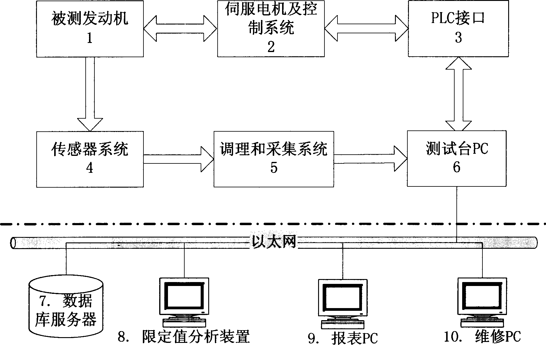
[0018] like figure 1 As shown, the engine test system of the present invention is composed of two parts: a test bench and an off-line data analysis device. The test bench is composed of servo motor and control system 2, PLC interface 3, sensor system 4, conditioning and acquisition interface 5, and test computer 6. In order to carry out automated testing, the test bench also includes fixtures, positioning devices, engine loading mechanisms, etc. (not shown in the figure).

[0019] The off-line analysis device is composed of a database server 7 , a limit value analysis device 8 , a report PC 9 and a maintenance PC 10 .

[0020] The DC servo motor in the servo motor and control system 2 is connected with the flywheel of the engine und...


PUM


Abstract

The invention relates to an engine testing system and relative testing method, wherein it uses direct-current servo motor to rotate the tested engine; it uses sensor to collect relative data to be analyzed, to be calculated and compared with preset limit value, to judge if the tested engine is qualified. The invention can shorten the testing time, improve the producing efficiency, reduce the test cost and avoid pollution.

Description

technical field [0001] The invention relates to a test system for an automobile engine. The invention also relates to a testing method for the engine testing system. Background technique [0002] The engine test system is an essential testing process in the automobile engine production line. The traditional test system is the hot test, that is, to test the parameters of the engine under the condition of the engine burning and doing work, so as to judge whether the parts and assembly of the engine are qualified. This test method is not completely suitable for the needs of the production line, mainly due to the following shortcomings: 1) The test efficiency of the thermal test is low, and it is not suitable for the current mass production; 2) The test process needs to add fuel, cooling 3) Environmental pollution such as noise and exhaust gas are generated during the test. Contents of the invention [0003] The technical problem to be solved by the present invention is to ...

Claims


Application Information

Patent Timeline
Patent Type & Authority Applications(China)
IPC IPC(8): G01M15/00
Inventor 王立
Owner SHANGHAI W IBEDA HIGH TECH DEV
Learn More