Five-phase Nd-Fe-B permanent-magnetic generator for vehicle

A five-phase NdFeB permanent magnet generator technology, applied to synchronous motors with stationary armatures and rotating magnets, synchronous machine parts, magnetic circuit rotating parts, etc., can solve the problem of high cost, stable voltage and permanent The structure of the magnetic generator is complicated, etc., to achieve the effect of less reactive power loss, compact structure and large output power

Inactive Publication Date: 2006-12-27
SHANDONG UNIV OF TECH
View PDF1 Cites 4 Cited by
  • Summary
  • Abstract
  • Description
  • Claims
  • Application Information

AI Technical Summary

Problems solved by technology

The stabilized permanent magnet generator has complex structure and high cost, and its performance needs to be further improved

Method used


Image

  • Five-phase Nd-Fe-B permanent-magnetic generator for vehicle

Examples


Embodiment Construction

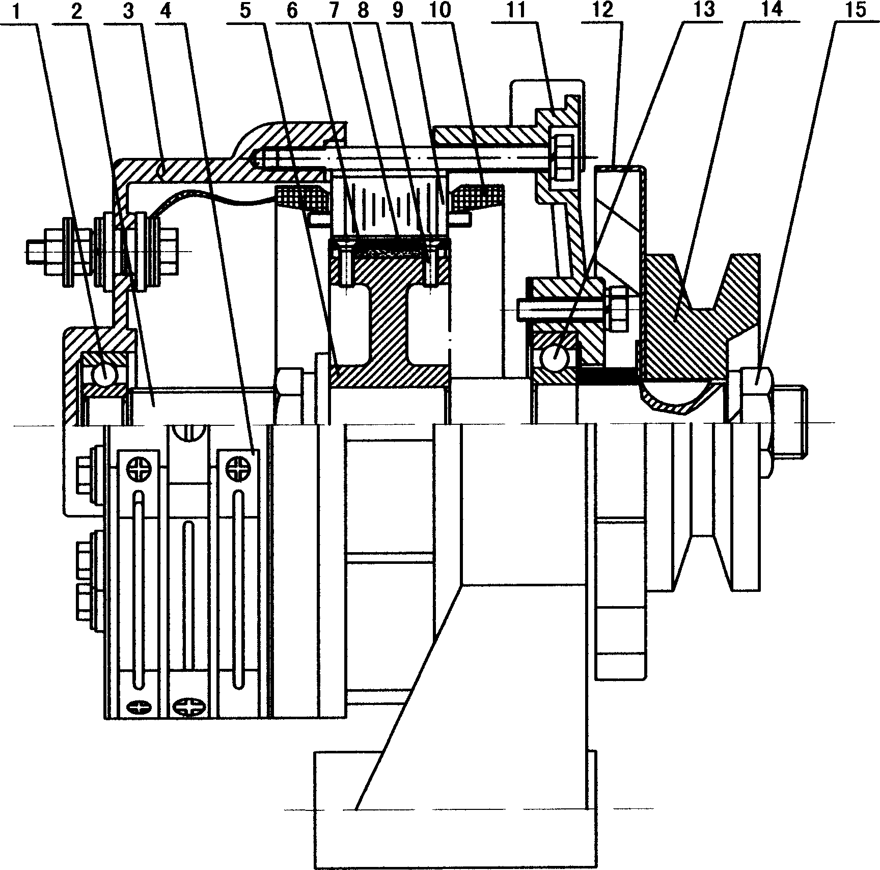
[0007] 1. Rear end bearing 2. Rotating shaft 3. Rear end cover 4. Electronic voltage stabilizer 5. Rotor core 6. NdFeB permanent magnet 7. Pole shoe 8. Non-magnetic screw 9. Stator core 10. Armature Winding 11. Front cover 12. Fan 13. Front bearing 14. Pulley 15. Nut

[0008] The present invention will be further described below in conjunction with accompanying drawing:

[0009] There are several poles on the stator core 9, and each phase of the armature windings 10 in the five identical armature windings 10 respectively straddles the five poles on the stator core 9 and inlays the wires sequentially, and the phase difference is 72° , the first end is connected to one point, which is the positive output end of the generator, and the tail end of each phase armature winding 10 is respectively connected to the input end of the five-phase half-wave controllable rectification and voltage stabilizing electronic voltage stabilizer 4 to form a five-phase In the NdFeB permanent magnet ...


PUM


Abstract

The provided five-phase Nd-Fe-B permanent-magnetic generator for vehicle comprises: the pole shoe, some permanent magnets with opposite polarity between near ones for N-S space array and every opposite to five poles on stator core, a rotor with iron core and shaft, and the stator composed by all of an iron core, a coiling, and a front / back cap. This invention has less wattless loss, compact structure for small room, and convenient to assemble for different vehicles.

Description

technical field [0001] The invention provides a five-phase NdFeB permanent magnet generator for vehicles, which belongs to the field of permanent magnet generators. Background technique [0002] The permanent magnet generators used with vehicles for a long time generally have the problems of poor low-speed power generation effect and low output power, which cannot meet the requirements of users. For example, the invention patent announced on August 8, 2001 in the Chinese Patent Gazette: Stabilized Permanent Magnet Generator, application number: 00112053.0, consists of a casing, a frame, a power shaft, a rotor, a permanent magnet steel, a stator, a stator winding, and a stator seat, stator sliding sleeve, balance spring, anti-rotation connecting screw, sliding block, adjusting shaft, positioning bearing, adjusting shaft driving mechanism and automatic feedback control circuit, etc. The power rotating shaft is fixed on the machine base through the positioning bearing, and the ...

Claims


Application Information

Patent Timeline
IPC IPC(8): H02K21/12H02K21/02H02K1/27H02K1/28H02K3/28
Inventor 张学义史立伟
Owner SHANDONG UNIV OF TECH
Why Eureka
Try Eureka