

Electric motor for a small-scale electrical appliance
A technology of electric motors and electrical appliances, which is applied in the field of electric motors, can solve the problems of limited changes, and achieve the effects of small shell swing, high vibration frequency, and simple structure
- Summary
- Abstract
- Description
- Claims
- Application Information
AI Technical Summary
Problems solved by technology
Method used
Image

Examples
Embodiment Construction
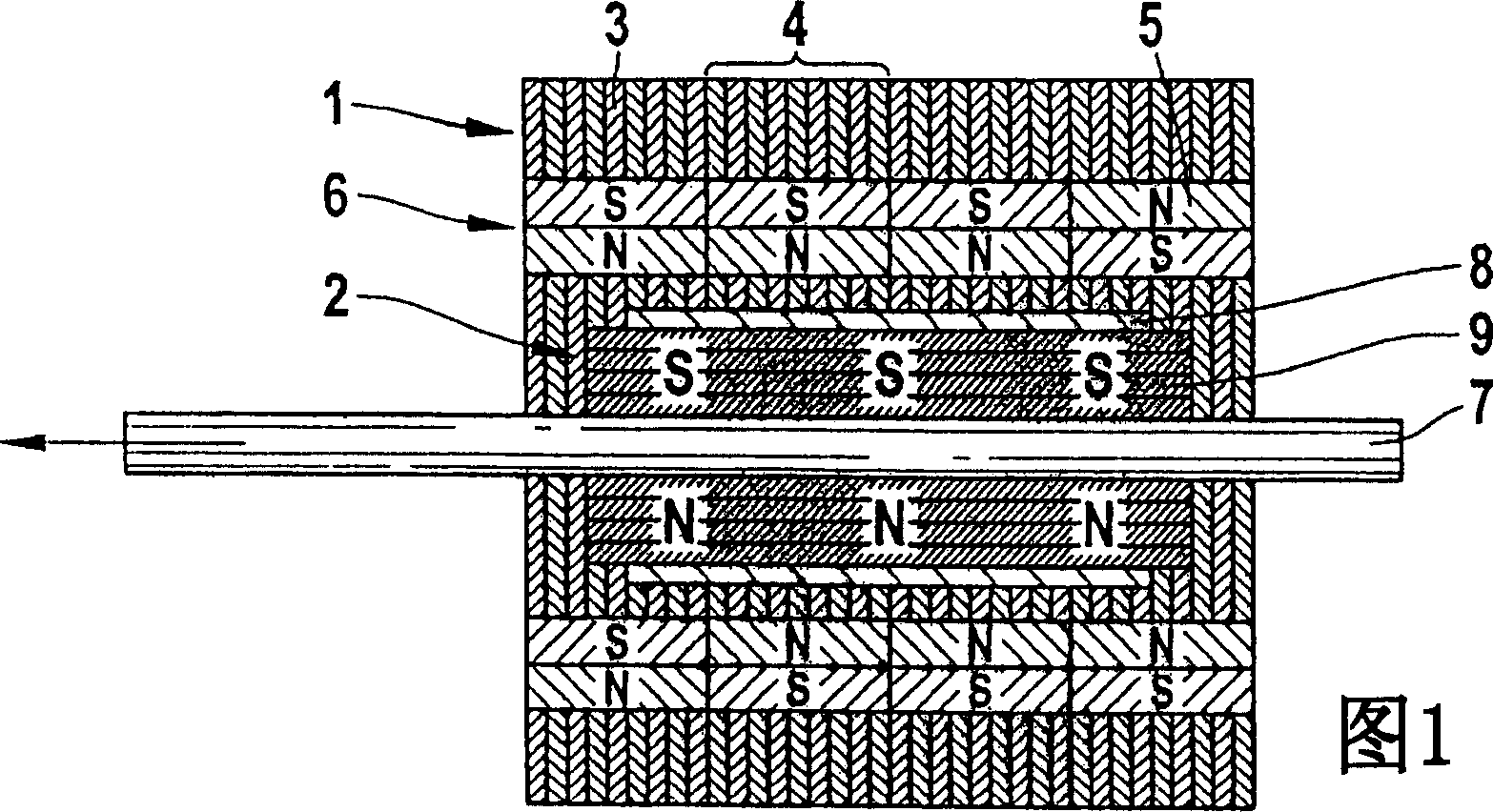
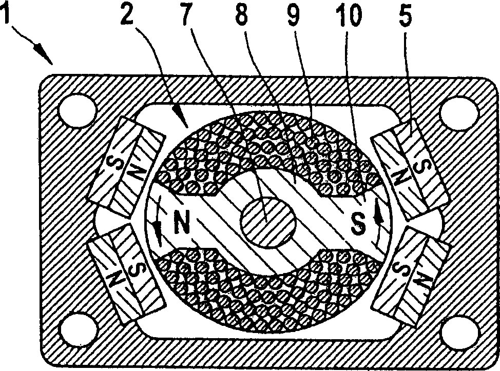
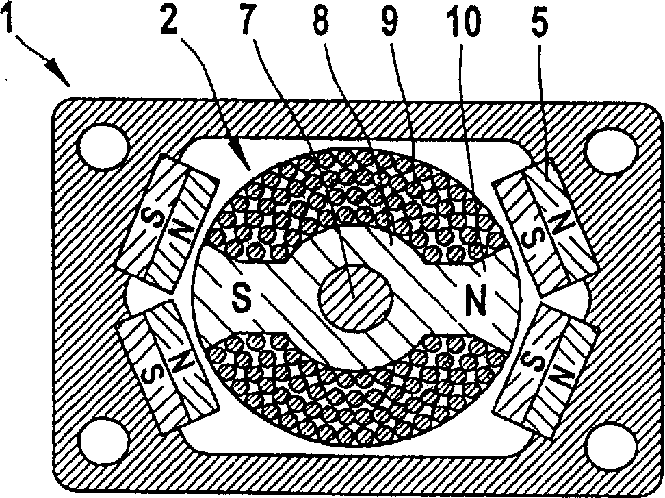
[0030] Fig. 1 is a schematic diagram of an embodiment of a motor according to the present invention. The electric motor has a stator 1 and a rotor 2 that is rotatable relative to the stator 1 and displaceable parallel to the axis of rotation. The stator 1 consists of a stack of soft iron laminations 3 , which form four axially juxtaposed segments 4 . Each segment 4 has a set of permanent magnets 5 distributed around the circumference of the stator 1 , which together form the magnetic means 6 of the stator 1 . The rotor 2 has an iron core 8 with a coil 9 arranged on a shaft 7 and is capable of both linear and rotational vibration movements relative to the stator 1 . In order to excite this vibrational movement, the coil 9 is supplied with a current signal. A magnetic field is formed in particular in the region of the iron core 8 by the current through the coil 9 and the iron core 8 is thus temporarily magnetized. Due to the magnetic interaction between the magnetized iron co...
PUM
 Abstract
Description
Claims
Application Information