Electric motor for a small-scale electrical appliance

A technology of electric motors and electrical appliances, applied in the field of electric motors, can solve the problems of limited changes and achieve the effect of small shell swing, simple structure and high vibration frequency

Active Publication Date: 2010-05-12
BRAUN AG
View PDF8 Cites 2 Cited by
  • Summary
  • Abstract
  • Description
  • Claims
  • Application Information

AI Technical Summary

Problems solved by technology

Also the rotation of the vibration always has the same frequency as the linear vibration, so the possibility of variation is very limited

Method used


Image

  • Electric motor for a small-scale electrical appliance
  • Electric motor for a small-scale electrical appliance
  • Electric motor for a small-scale electrical appliance

Examples


Embodiment Construction

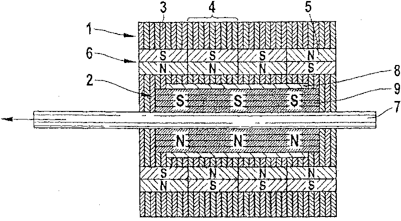
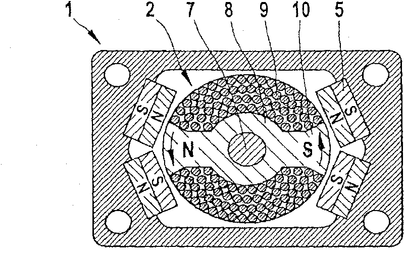
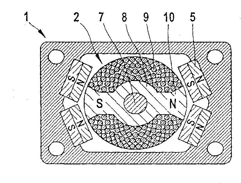
[0030] figure 1 is a schematic diagram of the principle of an embodiment of the motor according to the present invention. The electric motor has a stator 1 and a rotor 2 that is rotatable relative to the stator 1 and displaceable parallel to the axis of rotation. The stator 1 consists of a stack of soft iron laminations 3 , which form four axially juxtaposed segments 4 . Each segment 4 has a set of permanent magnets 5 distributed around the circumference of the stator 1 , which together form the magnetic means 6 of the stator 1 . The rotor 2 has an iron core 8 with a coil 9 arranged on a shaft 7 and is capable of both linear and rotational vibration movements relative to the stator 1 . In order to excite this vibrational movement, the coil 9 is supplied with a current signal. A magnetic field is formed in particular in the region of the iron core 8 by the current through the coil 9 and the iron core 8 is thus temporarily magnetized. Due to the magnetic interaction between ...


PUM


Abstract

The invention relates to an electric motor for an electrical small-scale unit. Said electric motor comprises at least one oscillatory motor component (1, 2), a magnet arrangement (6) comprising at least one permanent magnet (5), and a coil (9) for producing a magnetic field that generates a force for stimulating a linear oscillatory movement during interaction with the magnetic arrangement (6). The inventive electric motor is characterised in that a torque for stimulating a rotary oscillatory movement is also generated during the interaction of the magnetic field produced by the coil (9) and the magnet arrangement (6).

Description

technical field [0001] The invention relates to a motor for small electric appliances. Furthermore, the invention relates to a small electrical appliance having such an electric motor and to a method for operating the electric motor. Background technique [0002] Motors for small electric appliances are known in various configurations. For example DE 1 151 307 A discloses a vibrating armature drive mechanism for a dry shaver with a shaving cutter capable of reciprocating working movement, which mechanism has a U-shaped electromagnet fixedly connected to the housing of the shaver . A working armature is arranged near the magnetic poles of the electromagnet, and a compensation armature is respectively arranged on both sides of the working armature. In the operating state, the working armature, which drives the shaving cutter, oscillates parallel to the magnetic surface of the electromagnet, wherein the compensation armature vibrates in antiphase to this, in order to prevent...

Claims


Application Information

Patent Timeline
Patent Type & Authority Patents(China)
IPC IPC(8): H02K33/16H02K33/18
CPCH02K2201/18H02K33/18
Inventor 贝恩哈德·克劳斯汉斯约尔格·赖克乌韦·舍贝尔亚历山大·施勒特尔
Owner BRAUN AG
Why Eureka
Try Eureka