Spindle combine structure for gear compressor

A compressor and gear type technology, applied in the field of shaft combination structure of gear type compressors, can solve the problems of difficult component processing and assembly, shortened component life, power loss, etc. The effect of assembly tolerances

Inactive Publication Date: 2007-01-03
LG ELECTRONICS (TIANJIN) APPLIANCES CO LTD
View PDF0 Cites 2 Cited by
  • Summary
  • Abstract
  • Description
  • Claims
  • Application Information

AI Technical Summary

Problems solved by technology

The assembly and processing tolerances of the various parts constituting the compression part require such tolerances, so the processing and assembly of the parts are very difficult
[0022] In particular, in the structure of the compression part as described above, since the inner gear 30 and the rotating shaft 40 are press-fitted and fixed, when the inner gear 30 and the rotating shaft 40 are assembled with other components, as in image 3 As shown, when the center of the rotating shaft 40 is eccentric, not only frictional force is increased between the rotating shaft 40 and the upper and lower bearings 60 and between the inner gear 30 and the upper and lower bearings 60, but also wear occurs, so there is power loss and shortening. Component life issues

Method used


Image

  • Spindle combine structure for gear compressor
  • Spindle combine structure for gear compressor
  • Spindle combine structure for gear compressor

Examples


Embodiment Construction

[0039] Hereinafter, embodiments of the shaft coupling structure of the gear chamber compressor according to the present invention will be described in detail with reference to the accompanying drawings.

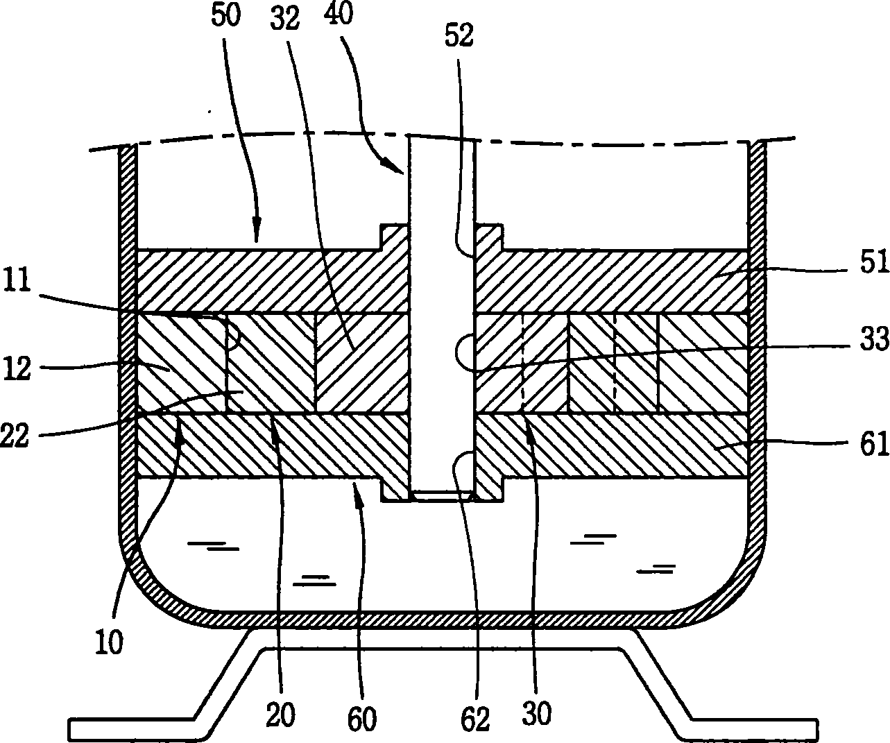
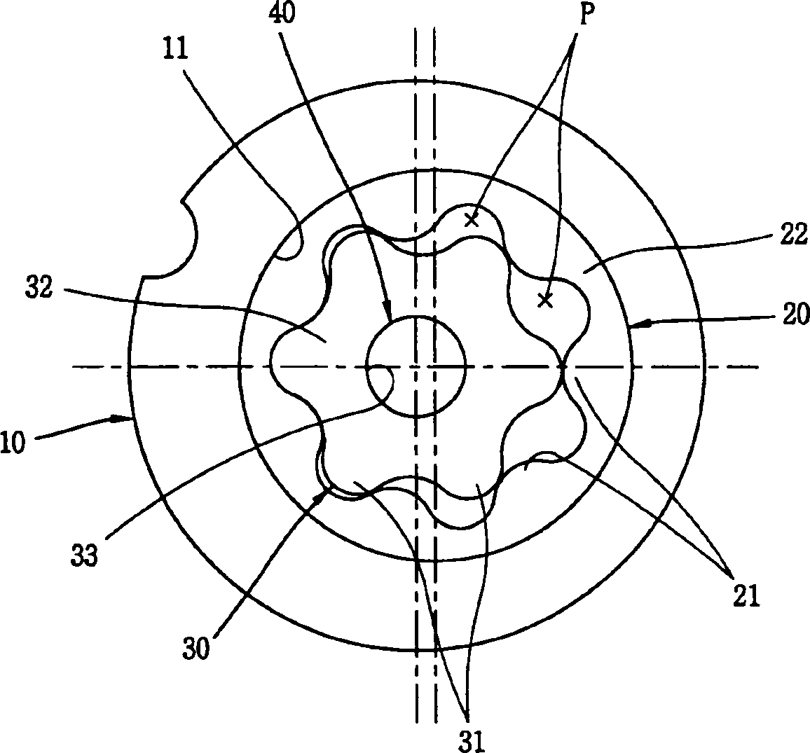
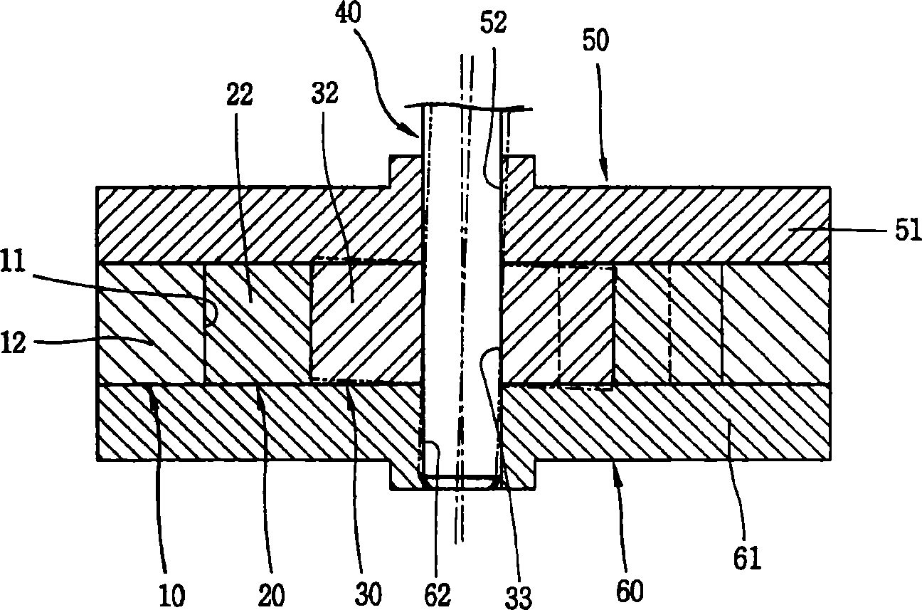
[0040] Figure 4 , 5 It is a front sectional view and a plan view of a compression part of a gear compressor having an embodiment of the gear compressor shaft coupling structure of the present invention.

[0041] As shown in the figure, firstly, the compression part of the above-mentioned gear compressor includes: a cylinder 10 with a gear insertion hole 11 formed inside it; Inserted into the gear insertion hole 11 of the above-mentioned cylinder 10; the inner gear 30, which has a plurality of gear teeth formed on its outer peripheral surface, is rotatably inserted into the above-mentioned outer gear 20 to form a plurality of compression spaces P together with the gear teeth 21 of the above-mentioned outer gear 20 The rotating shaft 40 is inserted and combined with the inne...


PUM


Abstract

The present invention provides a shaft combination structure of gear compressor. It includes the following several portions: cylinder, outside gear, inside gear, upper bearing, lower bearing and rotary shaft. On the described inside gear a shaft inserting hole is set, and on the described rotary shaft a combination portion is set, said combination portion is inserted into the shaft inserting hole of inside gear and can be used for transferring the rotation force of the rotary shaft to the inside gear, and said combination portion only can be moved towards one side direction of inside gear shaft inserting hole. Said structure can implement accurate contact between inside gear and outside gear, can inhibit leakage of compressed air and can raise compression efficiency.

Description

technical field [0001] The present invention relates to a gear type compressor, in particular to a shaft coupling structure of a gear type compressor capable of reducing friction between constituent parts and minimizing wear of the parts, and in addition, enabling easy assembly of the parts. Background technique [0002] In general, a compressor converts electrical energy into kinetic energy, and compresses refrigerant gas with the kinetic energy. The compressor is the core component of the refrigeration cycle system. According to the mechanism of compressing the refrigerant, it can be divided into rotary compressor, scroll compressor, reciprocal compressor, etc. type. These compressors are used in refrigerators, air conditioners, shop windows, etc. [0003] In the rotary compressor described above, the rotational force of the drive motor is transmitted to the rotating shaft to rotate the rotating shaft, and the eccentric portion provided on the rotating shaft side rotates...

Claims


Application Information

Patent Timeline
Patent Type & Authority Applications(China)
IPC IPC(8): F04C29/00F04C18/10
Inventor 金敬晧车刚旭姜胜敏裵英珠
Owner LG ELECTRONICS (TIANJIN) APPLIANCES CO LTD
Why Eureka
Try Eureka