

Lever-type traction bed
A traction bed and lever-type technology, applied in the field of traction bed, can solve the problems of increasing the pain of patients, increasing the difficulty of treatment, and failing to achieve the therapeutic effect, and achieve the effect of increasing the pain and being beneficial to the treatment.
- Summary
- Abstract
- Description
- Claims
- Application Information
AI Technical Summary
Problems solved by technology
Method used
Image

Examples
Embodiment 1
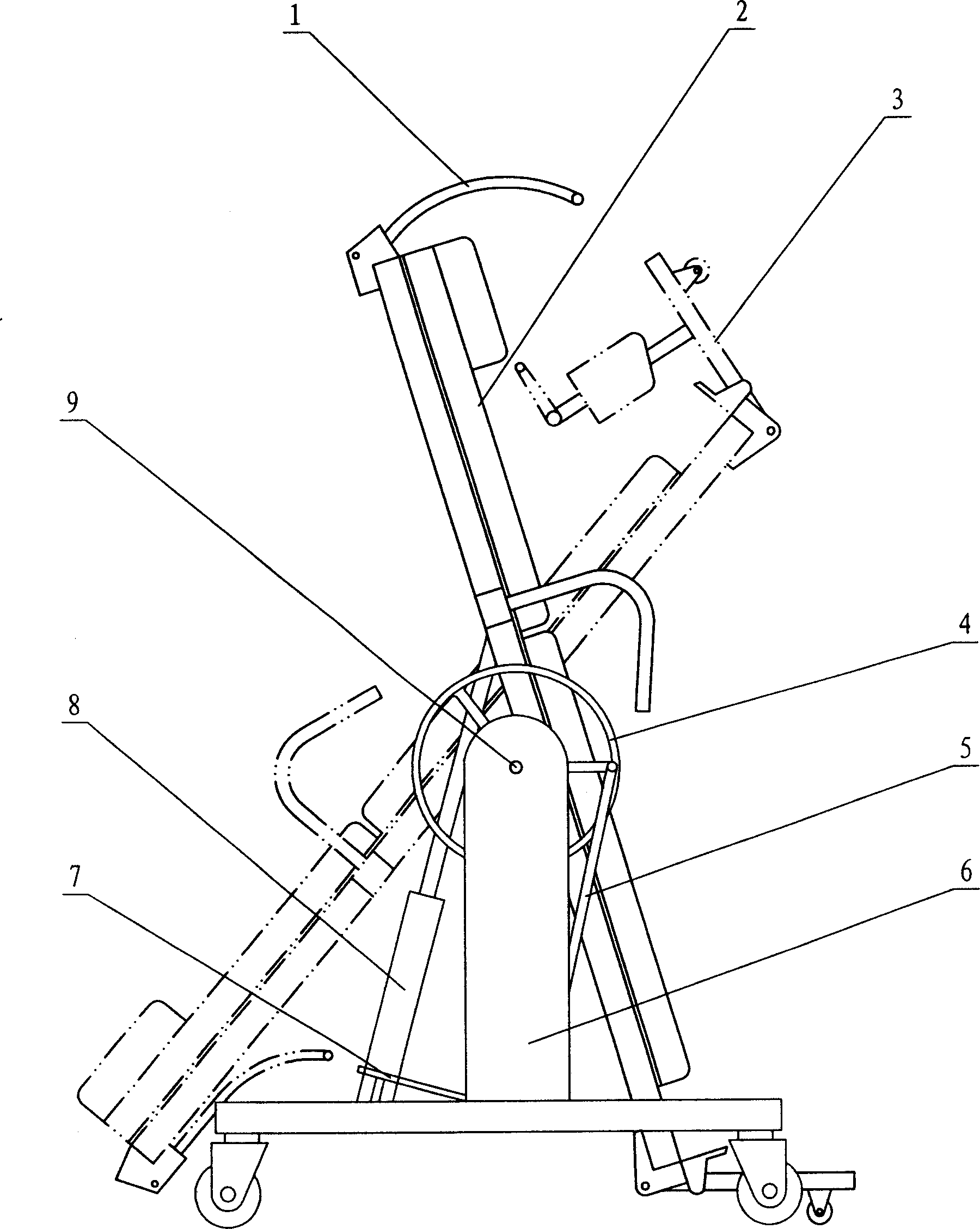
[0009] Embodiment 1: The driving mechanism is a hydraulic lever type traction bed
[0010] see figure 1 , the bed surface is composed of two sliding bed boards 3, the sliding bed boards are set in the slideway of the bedside frame, so that the sliding bedboard can slide in the slideway, and the bed surface is provided with a sling frame 1 and a foot stand 2, which are used for positioning the patient, The fulcrum structure that is provided with under the bed surface is that the bed surface is installed on the supporting seat 6 through the hinge 9 . The mechanism that drives the bed surface to rotate around the axis is a hydraulic jack 8, which is placed under the bed surface, the jack pressure bar 7, the connecting rod 5 and the hand wheel 4 are hinged in turn, and the hand wheel is arranged on the support seat. The patient lies flat on the bed, uses the sling to position the patient, turns the hand wheel back and forth, drives the jack pressure rod, and the jack rotates the ...
Embodiment 2
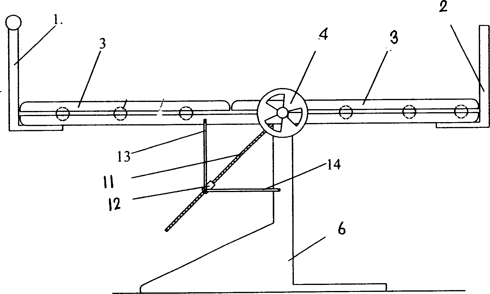
[0012] Embodiment 2: The driving mechanism is a lever-type traction bed with four linkages
[0013] see figure 2 , the mechanism that drives the bed surface to rotate around the axis can also be a four-bar linkage mechanism, that is, the support bed surface and two connecting rods 13, 14 form a four-bar linkage mechanism, and its output point is composed of a screw 11 and a screw nut 12. The bevel gear of the lead screw meshes with the gear in the handwheel, drives the handwheel, the lead screw rotates, the screw nut moves, and drives the bed surface to rotate around the fulcrum. Others are the same as in Embodiment 1.
PUM
 Abstract
Description
Claims
Application Information