Squirrel-cage electromagnetic retarder

A retarder and squirrel-cage technology, which is applied in the field of squirrel-cage electromagnetic retarders, can solve the problems of power consumption defects, vehicle power can not meet the needs of use, bulky and other problems, and achieve the best braking efficiency effect

Inactive Publication Date: 2007-01-10
安徽光太实业集团有限公司
View PDF0 Cites 2 Cited by
  • Summary
  • Abstract
  • Description
  • Claims
  • Application Information

AI Technical Summary

Problems solved by technology

[0003] However, the current eddy current retarder is only used to solve the basic problem of vehicle braking, especially its large size and power consumption defects make the vehicle power un

Method used


Image

  • Squirrel-cage electromagnetic retarder
  • Squirrel-cage electromagnetic retarder
  • Squirrel-cage electromagnetic retarder

Examples


Embodiment Construction

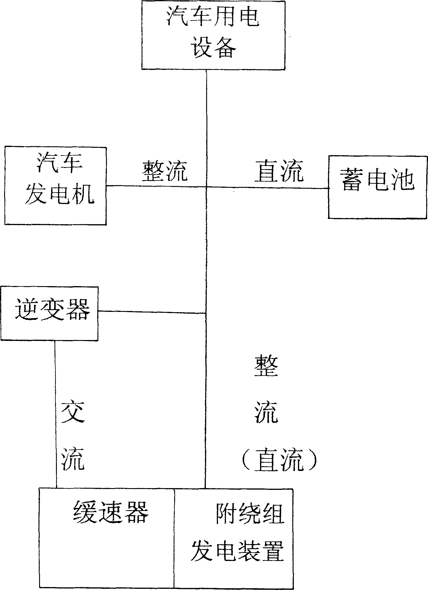
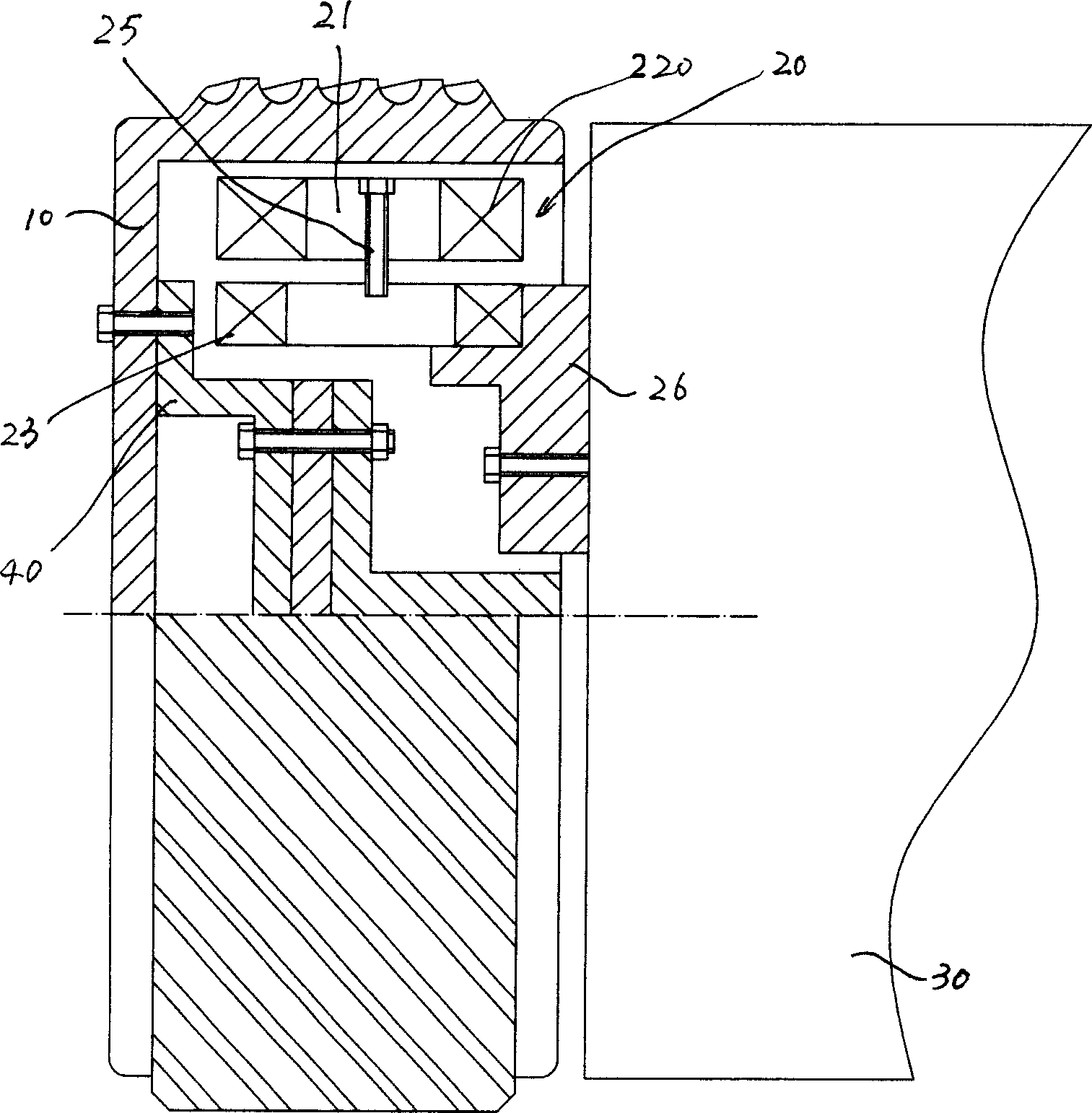
[0012] Such as figure 1 , 2 As shown, the squirrel-cage electromagnetic retarder of the present invention includes a rotor 10 and a stator 20, and the stator 20 includes a coil 22 arranged on a silicon steel sheet magnetic core 21, and a silicon steel sheet magnetic core 21 is also provided with The coil is attached to the winding 23, and the alternating current generated by the coil attached to the winding 23 is output to the consumer and the storage battery through the rectifier circuit.

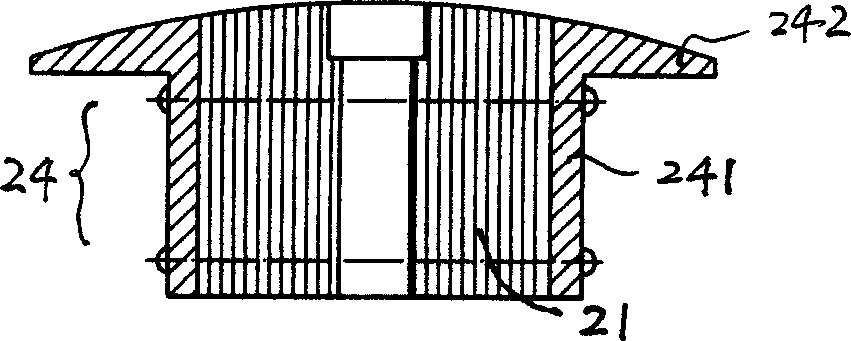
[0013] Such as image 3 , 4 , 5, the silicon steel sheet magnetic core 21 is located between the webs 241 of the frame plate steel 24, and the outer end of the frame plate steel 24 has wing plates 242 extending along both sides, and the silicon steel sheet magnetic core The middle part of the core 21 has radially arranged bolts 25 passing through and its inner end is connected with the coil attached winding 23 .

[0014] The webs 241 of the frame steel 24 on both sides are connected an...


PUM


Abstract

This invention relates to a cage electromagnetic buffer having the generation function and charging to levels at the same time including a rotor and a stator, in which, the stator includes a coil and an attached winding set on the core of silicon steel plates and the AC current generated by the winding is output to appliances and batteries via commutation circuit, thus, the electric energy produced by the attached winding can compensate energy cost when the buffer works and ensure the normal work of other appliances to get the best braking result.

Description

technical field [0001] The invention relates to a squirrel-cage electromagnetic retarder. Background technique [0002] The eddy current retarder involves a high-strength electromagnetic force, combined with a disk to convert the electromagnetic force into eddy current braking force for braking to achieve the effect of retarding. At present, in terms of technology, safety and noise, eddy current retarders have shown obvious advantages over traditional drum and disc brake devices, so they have developed rapidly in the field of automobile industry. Especially with the sharp increase of large, heavy-duty and long-distance vehicles, the eddy current retarder shows its unique advantages. [0003] However, the current eddy current retarder is only used to solve the basic problem of vehicle braking, especially its large size and power consumption defects make the vehicle power unable to meet the needs of use, resulting in the vehicle battery storage is always in a state of loss ,...

Claims


Application Information

Patent Timeline
IPC IPC(8): B60L7/28H02K49/04
CPCY02T10/641Y02T10/64
Inventor 王光太陈传松
Owner 安徽光太实业集团有限公司
Why Eureka
Try Eureka