
Electric vehicle speed reducer

A technology for electric vehicles and reducers, which is applied in the direction of electric vehicles, electric components, vehicle components, etc., and can solve problems such as unreasonable transmission ratio distribution curves and increased motor rotation angles

Inactive Publication Date: 2007-01-10
扬州金轮铁路器材有限公司
View PDF0 Cites 14 Cited by
  • Summary
  • Abstract
  • Description
  • Claims
  • Application Information

AI Technical Summary

Problems solved by technology

[0004] The present invention provides a method for solving the four major problems existing in the electric vehicle reducer, the method is: between the output end of the motor and the big bell crank and / or between the output end of the motor and the motor In order to improve the transmission ratio between the motor output end or the motor to the large crank throw and improve the unreasonable distribution curve of the transmission ratio between the motor output end or the motor to the large crank throw, increase the rotation angle of the motor from the relief position to the braking position, and in the system One or more parts of the system adopt buffer design, adopt non-rigid force transmission method in the force transmission process of the system, and add support devices in the transmission system so that the system transmits the force in the direction of the motor shaft except the torque through the support as much as possible. The device is directly or indirectly transmitted to the frame, adding a deceleration device to the transmission system, reducing the mass and speed of the moving parts in the system, reducing the radius of the rotating parts, reducing the inertia or moment of inertia of the moving parts, and improving the conductivity of the motor magnetic circuit. The magnetic capacity and / or improve the electrical conductivity of the motor’s conductive layer, and the external rotor motor should allow both ends of the motor rotor to be supported and / or allow both ends of the stator to be supported. The method is further explained in eight aspects as follows:

Method used


Image

  • Electric vehicle speed reducer
  • Electric vehicle speed reducer
  • Electric vehicle speed reducer

Examples


Embodiment Construction

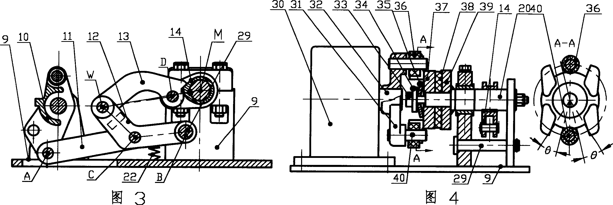
[0070] As shown in Figure 1, Figure 2, Figure 5, Figure 7 and Figure 10, the moving rail 1, the brake caliper 2, the rail bearing seat 3, the small bell crank 4, the small support 5, the basic rail 6, and the front tie rod 8, back pull dry 7, big bottom plate 9, big zigzag 10, roller 23. When the output end of the motor rotates forward or reversely, the big zigzag 10 is driven forward or reversely by a star-shaped five-bar linkage mechanism or an out-of-center star-shaped five-bar linkage mechanism or a swing rod, a swing arm booster mechanism or other booster mechanisms. The crank 10 is hinged on the large bottom plate 9, the big crank 10 drives the small crank 4 to rotate forward or reversely through the front pull rod 8 and the rear pull rod 7, and the big crank and the small crank push the brake caliper 2 to rise or Lowered, the brake caliper 2 drives the brake rail 1 fixed on it to move, and completes the braking and relief of the deceleration of the electric vehicle, in ...


PUM


Abstract

The invention provides a method for solving the existing problems of a motor vehicle reducer, such as motor shaft breakage, heart sweeping, and non-relief and heavy current caused by small transmission ratio of motor or motor output end to large crank and unreasonable distribution curve of transmission ratio, and designs several integrated or local solutions for the motor vehicle reducer.

Description

Technical field: [0001] The present invention relates to a speed regulating device used in railway hump marshalling yards, in particular to a six-bar linkage floating electric vehicle speed reducer used in railway hump marshalling yards. If the present invention is used in railway hump marshalling At the tail of the field, the equipment is also called a parking device, which is used for the anti-skidding of the railway to the hair line, and the equipment is also called the hair line anti-skid device. technical background: [0002] There are four major problems in the electric vehicle reducer originally used in the railway hump governor equipment: one is the problem of broken shaft of the motor; The small transmission ratio between the big crankshafts and the unreasonable distribution of transmission ratio partial curves cause the unrelief problem of the vehicle reducer, and the fourth is the problem of large motor current. These four major problems, especially the first two...

Claims


Application Information

Patent Timeline
Patent Type & Authority Applications(China)
IPC IPC(8): F16H37/00F16H21/12H02K1/02H02K1/12H02K5/02F16D7/02
CPCY02T10/641Y02T10/64
Inventor 丁红卫
Owner 扬州金轮铁路器材有限公司
Learn More