An intervertebral prosthesis

An intervertebral prosthetic and intervertebral technology, applied in the field of intervertebral prosthesis, can solve problems such as obstructing chisel or bone knife passage, and difficulty in detachment

Inactive Publication Date: 2007-01-10
WARSAW ORTHOPEDIC INC
View PDF11 Cites 5 Cited by
  • Summary
  • Abstract
  • Description
  • Claims
  • Application Information

AI Technical Summary

Problems solved by technology

[0010] However, this requires the application of a textured surface allowing bone ingrowth to the flat surface, and a device with protrusions from a ge...

Method used


Image

  • An intervertebral prosthesis
  • An intervertebral prosthesis
  • An intervertebral prosthesis

Examples


Embodiment 1

[0068] Example 1 - Prosthesis

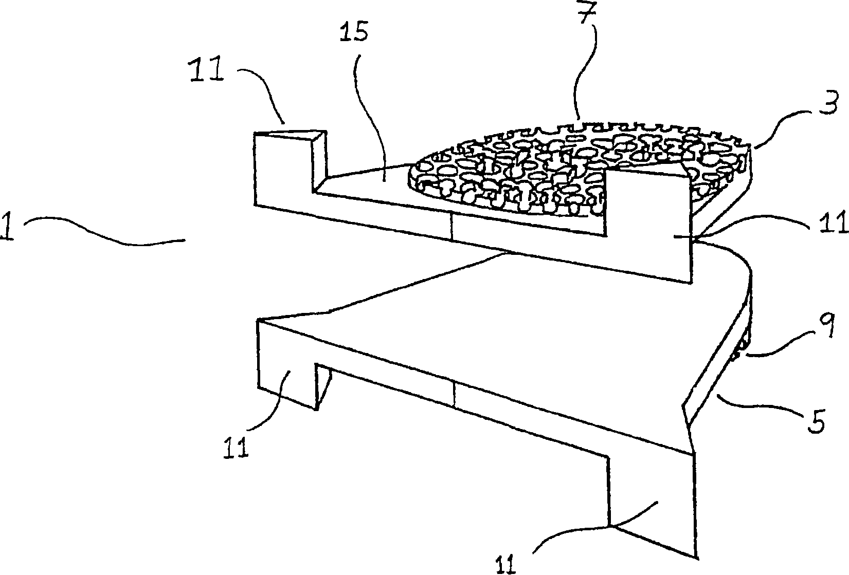
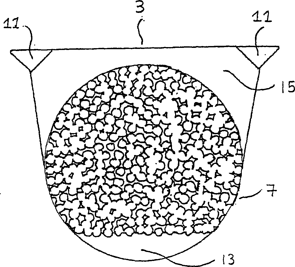
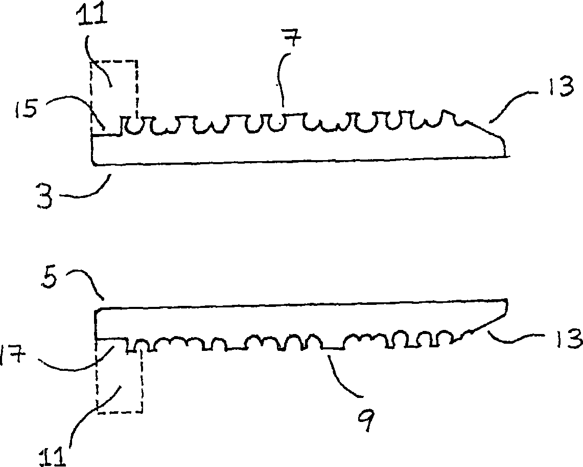
[0069] Intervertebral prosthesis 1 such as figure 1 As shown, it has a first plate 3 and a second plate 5 . The intervertebral prosthesis is made of titanium carbide. Plates 3 and 5 are articulated together by any suitable mechanism. In the prosthesis shown in Figure 4b, the ball and socket joint described in US Patent No. 6,113,637 is shown. Each plate 3 and 5 has a bone engaging surface 7 and 9 with a large textured surface. Large textured surface by e.g. Chem Tex  or Tecotex  It is formed by chemical texturing method and includes a surface with pores, wherein the radius of the pores is generally greater than 0.4mm. The large textured surface is roughly flat. The depths of the pores formed on the macro-textured surface are about the same, making the macro-textured surface substantially uniform.

[0070] Each plate 3 and 5 has a chamfered trailing edge 13, as figure 2 and 3 shown. The posterior edge 13 is the leading edge of the p...

Embodiment 2

[0074] Example 2 - Use of the prosthesis

[0075] The anesthetized patient is placed supine on the operating table with the neck held in a neutral position and neck traction applied using, for example, a Holter traction system. The anterior cervical spine is exposed at appropriate nodes by a transverse cervical incision.

[0076] Excision and decompression of the neck are performed in a conventional manner, and then the vertebral endplates are parallelized using a burrstone. Now release the neck traction.

[0077] Next, determine the disc gap depth and height using the abrasive test equipment of choice. A suitable grinding test apparatus 19 is shown in FIG. 5 . The grinding test device has approximately the same dimensions as the prosthesis 1 to be fitted, except that it is below the combined height of the large grains of the first plate 7 and the second plate 9 of the prosthesis, and that it is at a height corresponding to the convexity on the prosthesis 1. The position o...


PUM


Abstract

The application relates to an intervertebral prothesis. In particular, to an articulating intervertebral disc prothesis. In use, the intervertebral prosthesis is fixed to the end plates of vertebrae following the surgical excision of a degenerative or ruptured disc. The intervertebral prothesis has substantially flat bone engaging surfaces with a macro-textured surface.

Description

technical field [0001] The present invention relates to an intervertebral prosthesis. In particular, the present invention relates to an articulating intervertebral disc prosthesis. In use, the intervertebral prosthesis is secured to the endplates of the vertebrae after surgical removal of the degenerated or broken disc. The invention also relates to a method and a tool for inserting and removing the intervertebral prosthesis of the invention. Background technique [0002] Surgical treatment of spinal disorders usually involves removal of intervertebral discs. This is especially the case when there is degeneration or fragmentation of the disc, which contributes to compression of the spinal cord or nerve roots, resulting in neurological symptoms. After the disc is removed, the usual surgical procedure is to place a bone implant or insert an artificial fusion into the disc space to ensure proper spacing and alignment of the vertebrae. [0003] However, subsequent fusion of...

Claims


Application Information

Patent Timeline
IPC IPC(8): A61F2/44A61B17/16A61F2/46A61F2/00A61F2/30
CPCA61F2250/0025A61F2310/00089A61F2002/30322A61F2002/30576A61F2250/0026A61F2/4425A61F2002/30925A61F2310/00269A61B17/1659A61F2002/4619A61F2002/4627A61F2310/00017A61F2002/4623A61F2/4611A61F2/4684A61F2310/00023A61F2002/30321A61F2002/30769A61F2002/30616A61B17/1671A61F2002/4628A61F2002/4622A61F2002/30649A61F2/4603
Inventor 史蒂文·斯特里特菲尔德·吉尔
Owner WARSAW ORTHOPEDIC INC
Why Eureka
Try Eureka