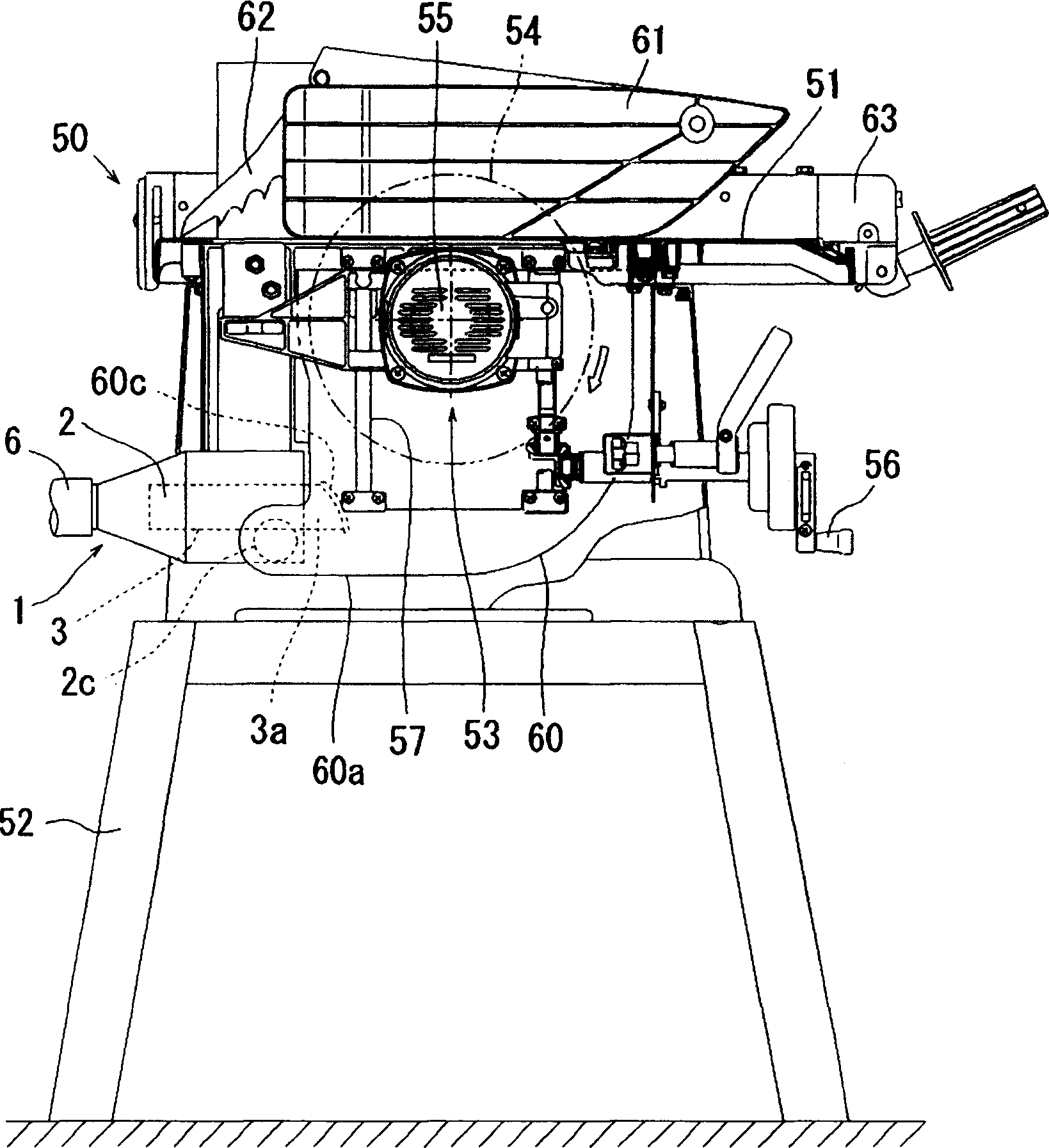
[0030] Below, based on Figure 1 to Figure 6 The embodiments of the present invention will be described. figure 1 The cutting machine 50 provided with the dust collector 1 of this embodiment is shown. The cutting machine 50 is a fixed circular saw disk called a table saw, and includes: a worktable 51 on which cutting materials are placed (not shown in the figure); a stand 52 which horizontally supports the worktable 51; and a cutting machine The main body 53 is installed on the upper part of the stand 52 and the lower side of the workbench 51.
[0031] The cutter main body 53 has circular serrations 54 and a motor 55 for rotating it. Such as figure 1 As shown by the hollow arrow, the serration 54 rotates in a clockwise direction. Furthermore, in figure 1 In this, the cut material is cut by moving from the right to the left.
[0032] The motor 55 is mounted on a base 58 which can move up and down in parallel via support columns 57 to 57 provided on the stand 52.
[0033] The upper part of the serration 54 protrudes upward from the surface of the table 51. The cutting material placed on the table 51 is moved toward the protruding portion to cut the cutting material.
[0034] Furthermore, by rotating the lifting handle 56 to move the base 58 up and down in parallel, the main body 53 of the cutting machine can be lifted up and down. By raising and lowering the main body 53 of the cutting machine, the protruding size of the saw teeth 54 from the upper surface of the table 51 can be changed, so that the cutting depth of the saw teeth 54 with respect to the cutting material can be adjusted.
[0035] The lower part of the serration 54 is covered by the blade housing 60. The blade housing 60 is formed long in the up and down direction, thereby allowing the saw teeth 54 to move within a certain range in the up and down direction. The dust collector 1 of this embodiment mentioned later is connected to the lower part of this blade housing 60.
[0036] The upper part of the serration 54 and the part protruding from the table 51 is covered by a cover 61. The cover 61 is arranged to be movable up and down, and because the cutting material enters the table 51, it is displaced upward and is in a state of abutting against the upper surface of the cutting material. The cover 61 covers the cut part and prevents the chips from flying upward.
[0037] In addition, on the table 51, in addition to the above-mentioned cover 61, a serrated knife 62 for preventing backlash is arranged.
[0038] Furthermore, the worktable 51 is equipped with a parallel gauge device 63 which has a guiding function for moving the cutting material placed on the worktable 51 in parallel.
[0039] The above-described structure of the upper surface of the table 51 and the lifting mechanism of the cutting machine main body 53 are the same as those of conventionally known structures, but it is sufficient. In the present embodiment, no particular changes are required, so detailed descriptions are omitted.
[0040] Next, the dust collecting device 1 of the present embodiment has a structure in which the swarf can be collected efficiently by the cyclone action. The cyclone effect in this specification refers to rotating the air stream containing the chips, and by generating centrifugal force, the chips with a density greater than air move radially outward (the inner wall surface side of the outer cylinder 2 described later) to move from The role of air for separation.
[0041] Figure 3 to Figure 6 The dust collector 1 of this embodiment is shown. The dust collecting device 1 includes a cylindrical outer tube 2 and an inner tube 3 arranged along the center C0 of the outer tube 2. One end side of the outer cylinder 2 is blocked by the cover part 2a. The inner cylinder 3 is fixed to the center C0 of the cover 2a. The inner tube 3 protrudes from the inside of the outer tube 2 to the outside through the cover portion 2a. This end protruding to the outside is opened to the atmosphere and becomes the exhaust port 3a. As shown in the figure, the end of the exhaust port 3a has a circular arc shape. The circular arc shape of the exhaust port 3a is formed along a circular arc centered on the center C1 of the dust collecting port 2c described later.
[0042] The end of the inner tube 3 on the inner side of the outer tube 2 is open to the inside of the outer tube 2. Therefore, the inside of the outer cylinder 2 communicates with the outside through the inner cylinder 3.
[0043] The other end side of the outer cylinder 2 is formed in a conical shape, and a discharge port 2b is provided at the front end.
[0044] On the peripheral surface (side surface) of the outer cylinder 2, a circular dust collecting port 2c is provided. Such as Figure 3 ~ Figure 6 As shown, the dust collection port 2c is arranged at an eccentric position relative to the center C0 of the outer cylinder 2. Therefore, as described later, the airflow flowing in through the dust collecting port 2c forms a swirling airflow around the inner tube 3 inside the outer tube 2. Such as Figure 4 As shown, the center C1 of the dust collection port 2c is eccentric to the right with respect to the center C0 of the outer cylinder 2. Therefore, such as Figure 4 As shown by the hollow arrow in the middle, the airflow flowing in through the dust collecting port 2c becomes a whirling airflow that rotates to the left with respect to the inner tube 3.
[0045] The dust collecting port 2c is connected to a connecting pipe portion 60a provided at the lower part of the blade housing 60. As shown in FIG. The front end of the connecting pipe portion 60a is relatively rotatable and airtightly inserted into the inner peripheral side of the dust collecting port 2c. Furthermore, the outer diameter size of the connecting pipe portion 60a and the inner diameter size of the dust collecting port 2c are appropriately set so as to provide an appropriate rotation resistance between the two. As described later, the outer cylinder 2 can be rotated around the center C1 of the connecting pipe portion 60a by the rotation resistance, and can be held at an arbitrary position.
[0046] Two engaging pins 2d and 2d are provided in the dust collecting port 2c. The two engagement pins 2d and 2d are respectively provided at positions facing each other in the circumferential direction in a state of protruding toward the inner circumferential side in the diameter direction. A ring 2e having elasticity is attached to the outer peripheral side of the dust collecting port 2c. This ring 2e prevents the two engagement pins 2d and 2d from falling off to the outer peripheral side.
[0047] On the other hand, on the outer peripheral surface of the front end of the connecting pipe portion 60a inserted into the inner peripheral side of the dust collecting port 2c, engaging recesses 60b, 60b are formed corresponding to the aforementioned engaging pins 2d, 2d. The two engagement recesses 60b and 60b are formed with a certain depth, and do not penetrate through the thickness direction of the connection pipe part 60a. The two engaging pins 2d, 2d are respectively inserted into the corresponding engaging recesses 60b. Two engagement recesses 60b and 60b are formed in a range of approximately 90 degrees in the circumferential direction.
[0048] Therefore, the dust collecting port 2c and the dust collecting device 1 are rotatably connected to the connecting pipe portion 60a within a range of about 90 degrees. Therefore, in the dust collecting device 1, the outer tube 2 and the inner tube 3 can move up and down. Direction of the vertical position ( image 3 The location shown, Figure 5 The position shown by the two-dot chain line in the middle) and the horizontal position along the horizontal direction ( Figure 6 The location shown, Figure 5 Rotate between the positions shown by the solid lines in). If the outer cylinder 2 and the inner cylinder 3 are located in the longitudinal position, the discharge port 2b faces downward. If the outer tube 2 and the inner tube 3 are positioned in the lateral position, the discharge port 2b faces the side.
[0049] Such as Figure 5 As shown by the middle solid line, if the outer cylinder 2 and the inner cylinder 3 are in the lateral position, the exhaust port 3a is blocked by the shielding plate 60c. Such as Figure 6 As shown, the shielding plate 60c is provided so as to extend laterally from the vicinity of the connecting pipe portion 60a of the blade housing 60. Again, such as Figure 5 As shown, the shielding plate 60c is bent along the same arc shape as the exhaust port 3a, so that the entire exhaust port 3a can be blocked substantially airtightly. By blocking the exhaust port 3a by the shielding plate 60c, the air leakage through the exhaust port 3a and the discharge of chips are prevented.
[0050] According to the dust collecting device 1 configured as described above, the air flow generated by the rotation of the saw teeth 54 blows the chips to the lower part of the blade housing 60, and the chips are generated by the cutting operation performed by the rotation of the saw teeth 54. The chips blown to the lower part of the blade housing 60 are efficiently collected by the dust collector 1. The dust collector 1 of this embodiment can be used by changing its direction to the vertical or horizontal direction.
[0051] First of all, such as figure 1 As shown, if the dust collecting device 1 is located in the longitudinal position and the outer cylinder 2 is in an up and down state, the cyclone action of the dust collecting device 1 can be used to efficiently collect dust. That is, the chips blown to the lower part of the blade housing 60 flow into the connecting pipe portion 60a by the airflow, and thereafter flow into the outer tube 2 of the dust collector 1. Such as Figure 4 As shown by the hollow arrow, the above-mentioned air flow flowing into the outer cylinder 2 forms a rotating flow that rotates to the left with respect to the inner cylinder 3. While the air containing chips rotates around the inner cylinder 3, the denser chips fall toward the lower discharge port 2b. On the other side, the less dense air passes through the lower end of the inner cylinder 3 and is discharged from the exhaust port 3a to the outside. Qi (cyclone effect). The chips are discharged through the discharge port 2b. The discharged chips are collected in a dust collecting box 5 provided below the dust collecting device 1. Furthermore, instead of the dust box 5, a dust bag may be provided below the discharge port 2b.
[0052] Secondly, such as figure 2 As shown, with the dust collector 1 in the horizontal position and the outer cylinder 2 in the horizontal direction, by connecting the dust collector 6 with the discharge port 2b, the dust collector 6 can be forced to collect and flow into the outside. Chips in the barrel 2. In this case, the exhaust port 3a is blocked by the shielding plate 60c, thereby preventing the chips from leaking from the exhaust port 3a. Therefore, the chips pass through the exhaust port 2b and are forcibly collected by the dust collector 6 for dust. Furthermore, in this case, unlike the case of the above-mentioned longitudinal position, the dust separated from the air flow is not discharged by the cyclone action, but the dust collector 6 forcibly sucks the air flow into the outer cylinder 2 and its effects. Containing chips.
[0053] As described above, according to the dust collecting device 1 of the present embodiment, the chips generated in the stationary cutting machine 50 called a table saw can be passed through the dust collecting device 1 (cyclone type dust collecting device 1) using the cyclone action. ) To collect dust efficiently.
[0054] Furthermore, in the dust collector 1 according to the illustrated embodiment, the connecting pipe portion 60a of the blade housing 60 can be rotated, and the outer cylinder 2 and the inner cylinder 3 can be rotated between the vertical position and the horizontal position. A method of forcibly collecting dust by connecting a dust collecting device or, for example, a dust collector using a cyclone effect, can be selectively adopted, so various usages in accordance with the working method can be adopted.
[0055] In the embodiment described above, various changes can be added. For example, the following configuration is exemplified: in a state where the connecting pipe portion 60a of the blade housing 60 is rotatable, the dust collection port 2c is connected, and the position can be changed between the vertical position and the horizontal position, but it may also be configured to: In a fixed position, connect the dust collector to the connecting pipe. In this case, the shielding plate 60c is not required. By fixing the outer cylinder and the inner cylinder in the longitudinal position, the chips blown into the blade housing are efficiently collected by the constant cyclone.
[0056] In addition, although the configuration in which the vertical position and the horizontal position can be changed by rotating the outer cylinder 2 and the inner cylinder 3 is illustrated, it may be configured to be temporarily removed from the connecting pipe portion 60a of the blade housing 60 and can be moved in the longitudinal direction. Change the position between the position and the horizontal position.
[0057] Furthermore, the configuration of the cutter main body 53 can be raised and lowered, the table 51 has a cover 61 and a serrated knife 62, etc., and the configuration of the cutter main body may be arbitrary, and appropriate changes may be added.