Eureka AIR delivers breakthrough ideas for toughest innovation challenges, trusted by R&D personnel around the world.

High-temperature superconductive power cable terminal

A power cable and high-temperature superconducting technology, which is applied to cable terminals, superconducting devices, superconducting/high-conducting conductors, etc., can solve problems such as inability to transport low-temperature liquids, inability to apply high-temperature superconducting cables, and inability to keep heat. Safety guarantee, simple and reliable insulation processing, and convenient transportation

Inactive Publication Date: 2007-01-17
INST OF ELECTRICAL ENG CHINESE ACAD OF SCI
View PDF0 Cites 6 Cited by
  • Summary
  • Abstract
  • Description
  • Claims
  • Application Information

AI Technical Summary

Problems solved by technology

The existing conventional cable terminal cannot transport cryogenic liquid inside, nor can it keep warm, and it cannot be applied to the requirements of high-temperature superconducting cables at all.

Method used


Image

  • High-temperature superconductive power cable terminal
  • High-temperature superconductive power cable terminal
  • High-temperature superconductive power cable terminal

Examples


Embodiment Construction

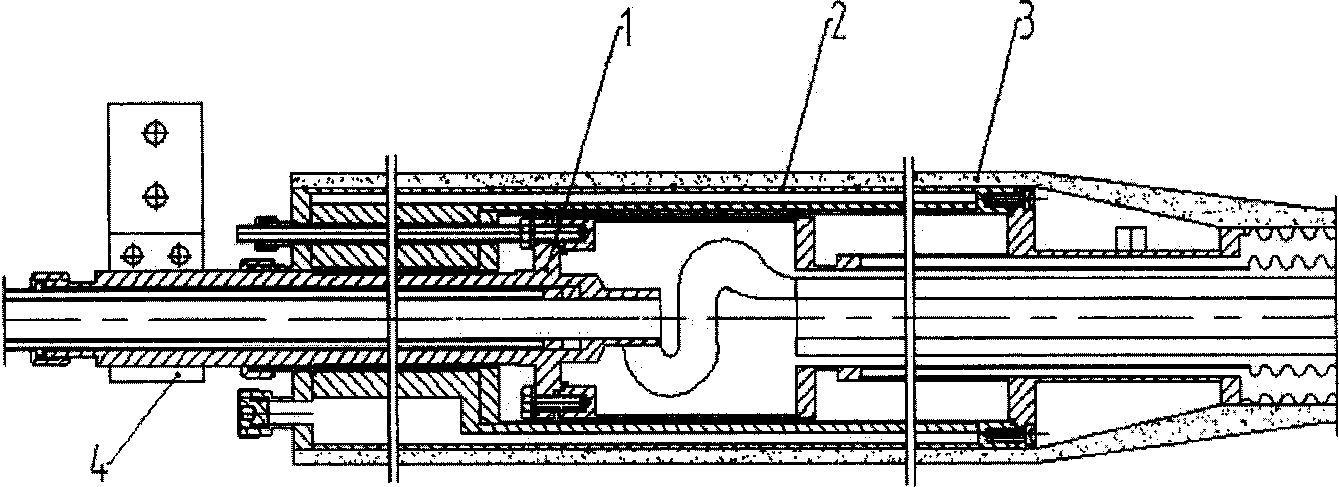
[0025] figure 1 Shown is the schematic structural diagram of the terminal of the present invention, which is composed of terminal internal parts 1, terminal insulation cover 2, insulating layer 3 and connection terminal 4. The terminal inner part 1, the terminal insulation cover 2 and the insulating layer 3 are coaxially placed sequentially from the inside to the outside. The terminal inner part 1 is located on its central axis, followed by the insulation cover 2, and the outermost layer is the insulating layer 3. The connection terminal 4 is fixed on the outer end of the terminal inner part 1 .

[0026] The function of the terminal internal part 1 is to output a large current, connect electrical measurement signals, and input liquid nitrogen for cooling superconducting cables. The function of the insulation cover 2 is to prevent the ambient temperature from being transmitted to the superconducting cable in the terminal, so as to realize the requirement of low-loss operation....


PUM


Abstract

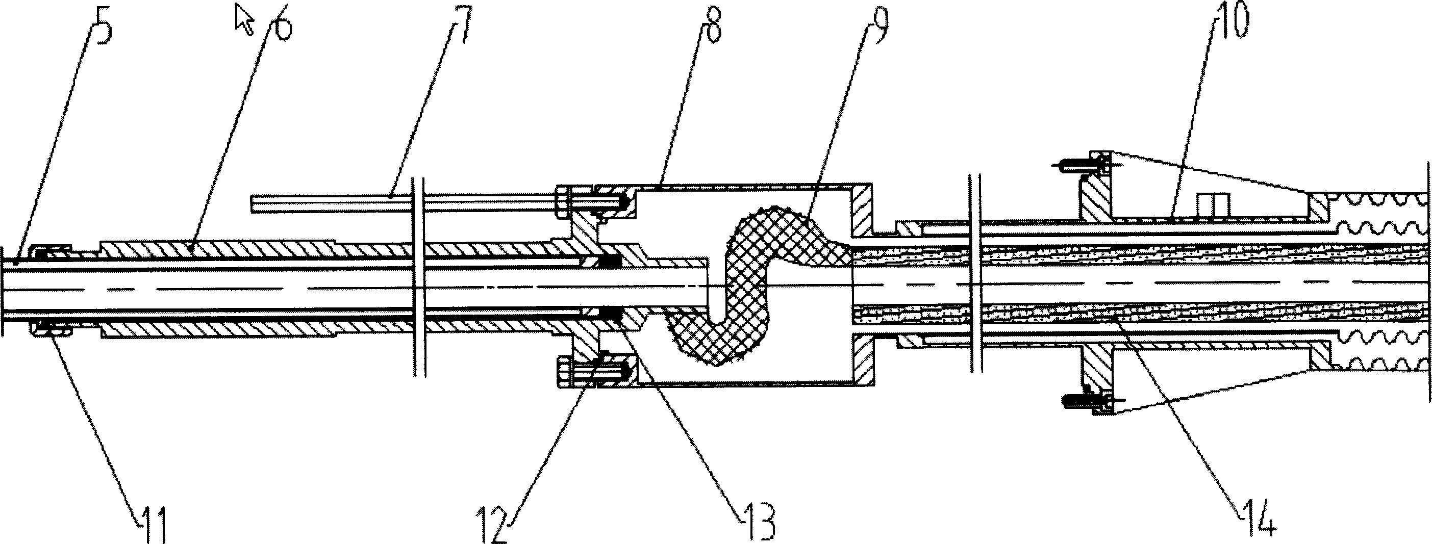
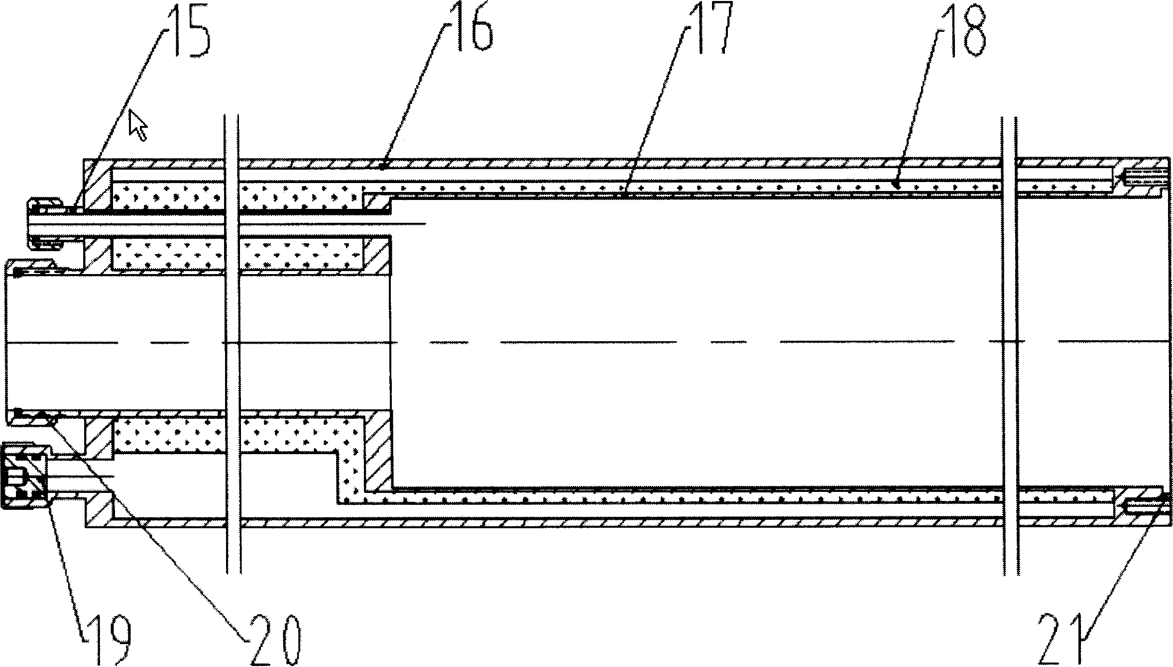
A high-temperature superconductivity cable terminal, including: the terminal inner parts (-), the terminal muff cover (-), the insulating layer (-) and the connection terminal (-); puts the terminal inner parts (-), the terminal muff cover (-) and the insulating layer (-) at the same axis in turn, the terminal inner parts (-) is located at the centre of the axes, and then is the terminal muff cover (-), the insulating layer (-) is at the outset layer. The terminal inner parts (-) consists of the liquid nitrogen liquid nitrogen conduit (-), the electric current lead (-), the flexible connecting line (-), the testing line (-), the inner cavity (-) and the sealing interface (-, -, -) between them. The electric current lead (-) connects with the inner cavity (-), the liquid nitrogen liquid nitrogen conduit (-) is located at the central axes of the electric current lead (-), the flexible connecting line (-) sets in the inner cavity (-), the testing line (-) is located at the out side of the electric current lead (-); the right end of the terminal inner parts (-) connects with the end part of the cable container (-);the liquid nitrogen liquid nitrogen conduit (-) inserts into the terminal inner cavity (-)from the inside of the electric current lead (-). Between the inner and outer two layer stainless steel tube (-, -) of the muff cover (-) puts the super heat-insulating material (-) and vacuumizes.

Description

technical field [0001] The invention relates to a high-temperature superconducting cable, in particular to a high-temperature superconducting power cable terminal. Background technique [0002] Using high-temperature superconducting power cables can realize low-loss, high-capacity power transmission, greatly reducing operating costs, and the application prospects are very promising. All technologically advanced countries are competing to carry out relevant research and development work, among which, the terminal of high temperature superconducting power cables is one of the key technologies of research and development. [0003] The high-temperature superconducting power cable terminal (hereinafter referred to as the terminal) is the two terminal parts of the superconducting cable. Its main function is to realize the introduction and output of large current, the input and output of low-temperature cooling liquid, and the extraction of various electrical measurement signals a...

Claims


Application Information

Patent Timeline
Patent Type & Authority Applications(China)
IPC IPC(8): H02G15/02H01B12/00
CPCY02E40/648Y02E40/64Y02E40/60
Inventor 高智远戴少涛张丰元许熙滕玉平林玉宝林良真肖立业
Owner INST OF ELECTRICAL ENG CHINESE ACAD OF SCI
Why Eureka
Eureka Blog
Learn More