Positive pressure explosion-proof box body

A positive pressure explosion-proof box technology, which is applied in the direction of casing/cabinet/drawer components, electrical components, sealed casings, etc., can solve the problems of non-explosion-proof function, inconvenient maintenance of positive pressure explosion-proof box, etc. , to achieve the effect of quick and easy opening and closing, reliable and simple installation, and convenient handling

Pending Publication Date: 2020-09-25
CHANGZHOU SHENGHE ELECTRONICS
View PDF11 Cites 0 Cited by
  • Summary
  • Abstract
  • Description
  • Claims
  • Application Information

AI Technical Summary

Problems solved by technology

The utility model of Chinese patent application number 201620407752.4 discloses a touch screen positive pressure explosion-proof box. The box body is provided with a touch screen installation port, a cable hole and an air source hole. The touch screen is installed at the touch screen installation port, and the communication cable passes through the cable hole. It enters the box and connects with the touch screen, and the gas source pipe passes through the gas source hole to fill the box with gas. The above-mentioned positive pressure explosion-proof box is inconvenient to open the box for maintenance.
At present, the box whose lid is fixed by magnetic suction generally does not have explosion-proof function.

Method used


Image

  • Positive pressure explosion-proof box body
  • Positive pressure explosion-proof box body
  • Positive pressure explosion-proof box body

Examples


Embodiment 1

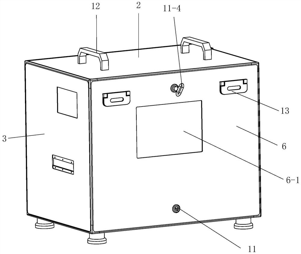
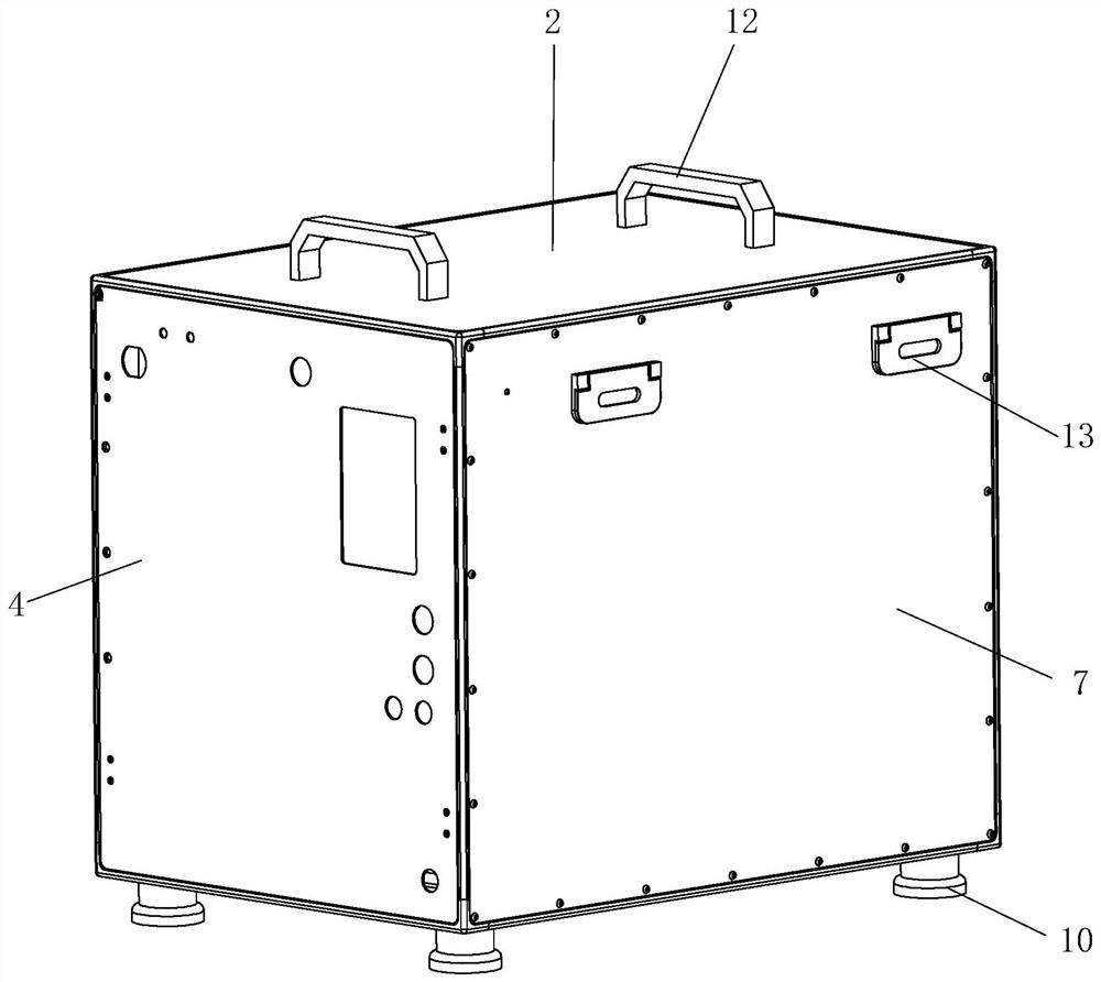
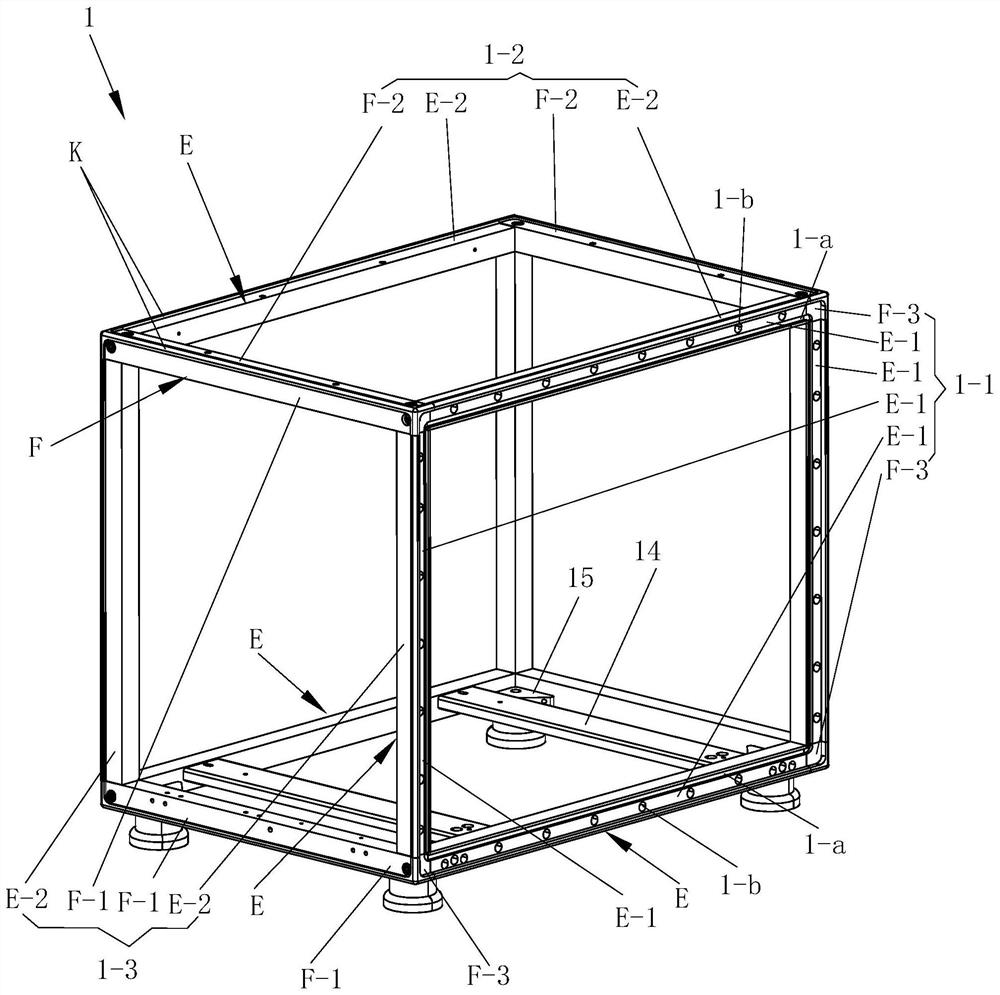
[0033] See Figure 1 to Figure 16 , The present embodiment comprises a three-dimensional frame 1, top, bottom, front and rear box panels that are respectively arranged on the three-dimensional frame, and side box panels 7 and box covers 6 that are respectively arranged on both sides of the three-dimensional frame. Stereoframe 1 comprises two planar frames A (see Figure 10 ), the two plane frames A are connected by four uprights through screws 16, and the uprights are I-type rods.

[0034] The first surface E-1 of the Type I rod is provided with a straight groove L-1 through both ends, and the surface away from the straight groove L-1 and perpendicular to the first surface E-1 of the Type I rod is the second surface E of the Type I rod -1. A flange K is provided at the junction of the first surface E-1 of the I-type rod and the second surface E-2 of the I-type rod.

[0035] The end face F-3 of the type II rod is provided with an arc groove L-2, and the two perpendicular surf...


PUM


Abstract

The present invention discloses a positive-pressure explosion-proof box body. The box body comprises a three-dimensional frame, the three-dimensional frame comprises two plane frames and four stand columns connected between the two plane frames, and a top box plate, a bottom box plate, a front box plate and a rear box plate are connected to the top, the bottom, the front face and the rear face ofthe three-dimensional frame respectively. Side box plates and a box cover are arranged on the two annular side faces of the three-dimensional frame respectively, annularly-arranged magnetic blocks arearranged on the annular side face, opposite to the box cover, of the three-dimensional frame, and the box cover is magnetically attracted to the three-dimensional frame. According to the box body, the positive pressure and pressure relief dual-pressure overload protection can be achieved, the safe work of the equipment in the explosion-proof box body is guaranteed; due to the magnetic connectionof the box cover, the box cover can be opened and closed quickly and easily, and convenience is brought to operation. The box body is particularly suitable for being used as a box body of a positive-pressure explosion-proof printing device, and a printer is installed in the box body, so that the paper adding, paper clamping and other treatment are convenient.

Description

technical field [0001] The invention relates to a positive pressure explosion-proof box body. Background technique [0002] Conventional explosion-proof equipment needs to be placed in an explosion-proof box and isolated from external hazardous places. For printers working in hazardous locations containing explosive gases, vapor mixtures or combustible dusts, in order to prevent the print head from generating instantaneous high temperature and high energy and igniting combustible gases and dusts, it is considered to be placed in an explosion-proof box. The printer needs to add paper, deal with paper jams, repair and other operations, all of which need to be unpacked. The utility model of Chinese patent application number 201620407752.4 discloses a touch screen positive pressure explosion-proof box. The box body is provided with a touch screen installation port, a cable hole and an air source hole. The touch screen is installed at the touch screen installation port, and the ...

Claims


Application Information

Patent Timeline
Patent Type & Authority Applications(China)
IPC IPC(8): H05K5/06H05K5/03H05K5/02
CPCH05K5/061H05K5/03H05K5/0217
Inventor 张荣杜立力曹云康封丽
Owner CHANGZHOU SHENGHE ELECTRONICS
Why Eureka
Try Eureka