
Core piece for exhaust gas catalyst device, method of producing the same, and method of installing and fixing the same

A technology of catalyst device and fixing method, which is applied in the direction of exhaust device, catalyst carrier, chemical instrument and method, etc., can solve the problems of increased weight, increased number of processes, increased cost of exhaust catalyst device 1', etc., and achieves processing cost Reduce and realize the effect of manufacturing process and enrich deformation

Active Publication Date: 2007-01-17
SAKURA IND
View PDF1 Cites 0 Cited by
  • Summary
  • Abstract
  • Description
  • Claims
  • Application Information

AI Technical Summary

Problems solved by technology

That is, in the manufacture of the above Figure 14 (a) In the case of the core member 3', the desired core member 3' is obtained by stacking metal plates such as a flat plate and a corrugated plate, and then rolling them into a spiral shape until reaching an appropriate size. However, by using such a method, Even if only the core member 3' is manufactured, many components are required, and the number of steps tends to increase due to the large number of components, which leads to an increase in cost or weight of the exhaust catalyst device 1'.

Method used


Image

  • Core piece for exhaust gas catalyst device, method of producing the same, and method of installing and fixing the same
  • Core piece for exhaust gas catalyst device, method of producing the same, and method of installing and fixing the same
  • Core piece for exhaust gas catalyst device, method of producing the same, and method of installing and fixing the same

Examples


Embodiment 1

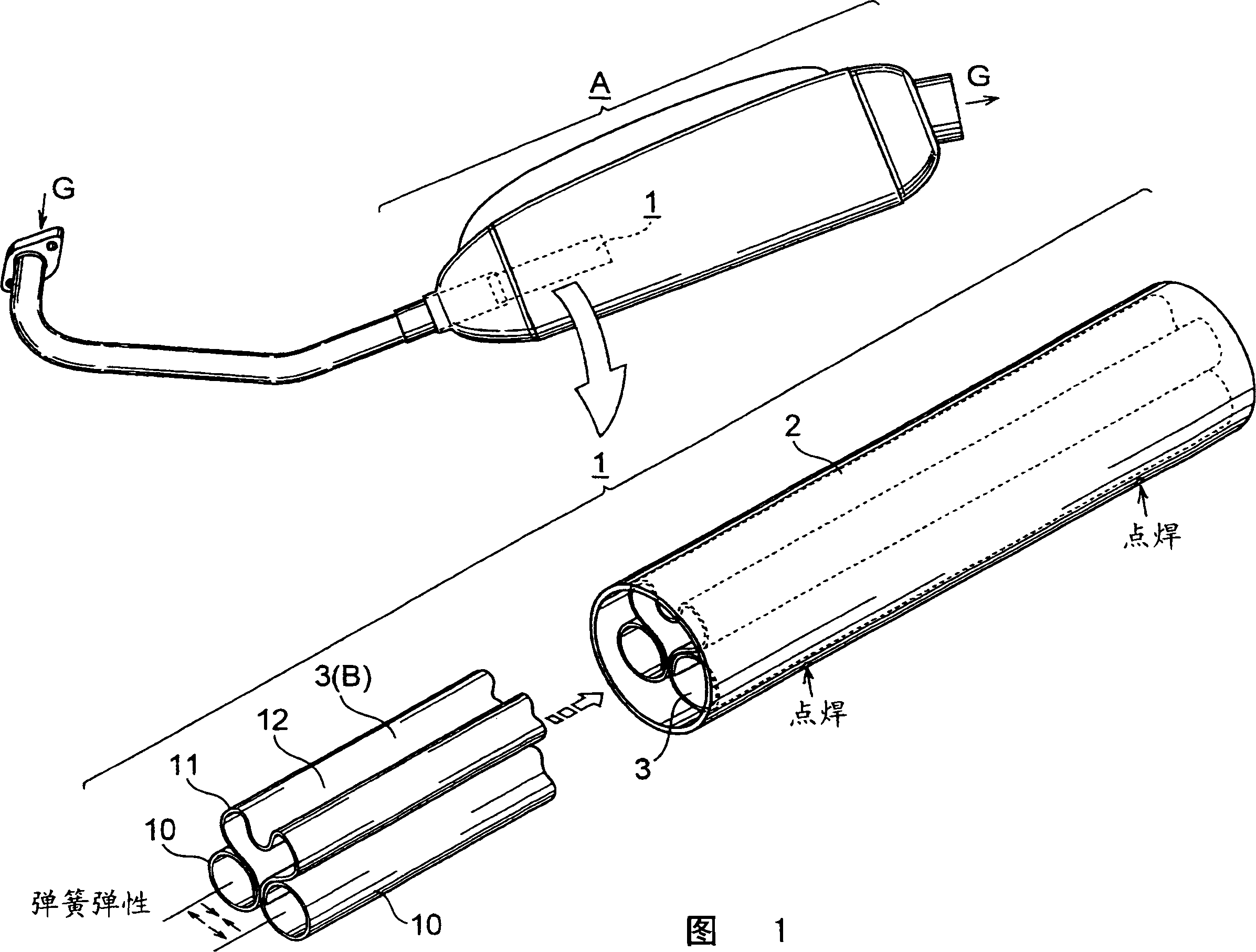
[0064] Embodiment 1 is an example in which the spring elasticity of the core 3 is used to realize the inserting and fixing of the core 3 as described above. When a deformation occurs, the deformation is restored to the outside. In other words, it is a cross-sectional shape that has a spring action that restores the pressing deformation generated inward to the outside. Therefore, the core 3 uses the cross-sectional shape of the component itself to achieve elastic installation to the outer cylinder 2, so as to be inserted into the outer cylinder 2 The status of is fixed (insert fixed).

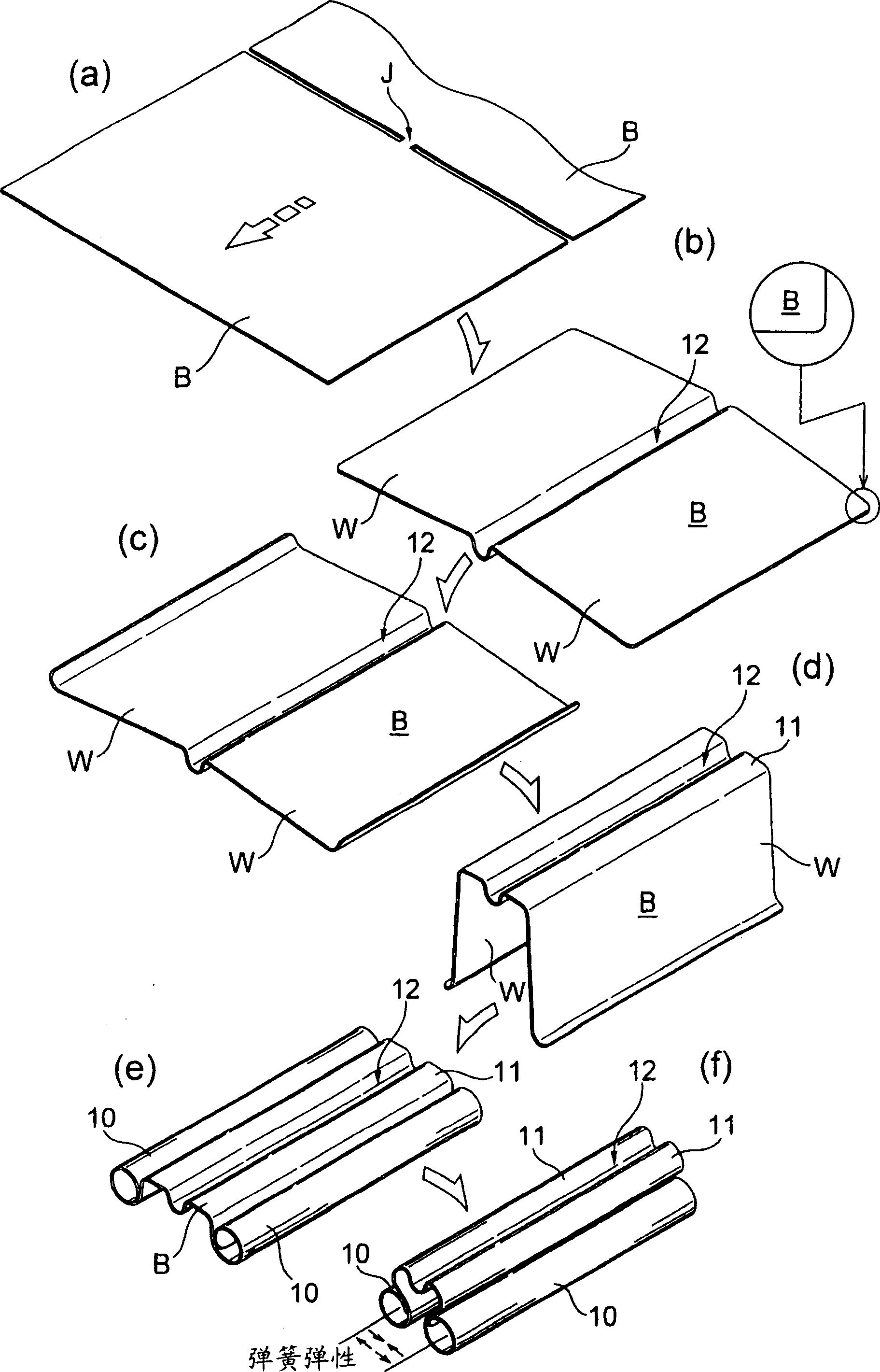
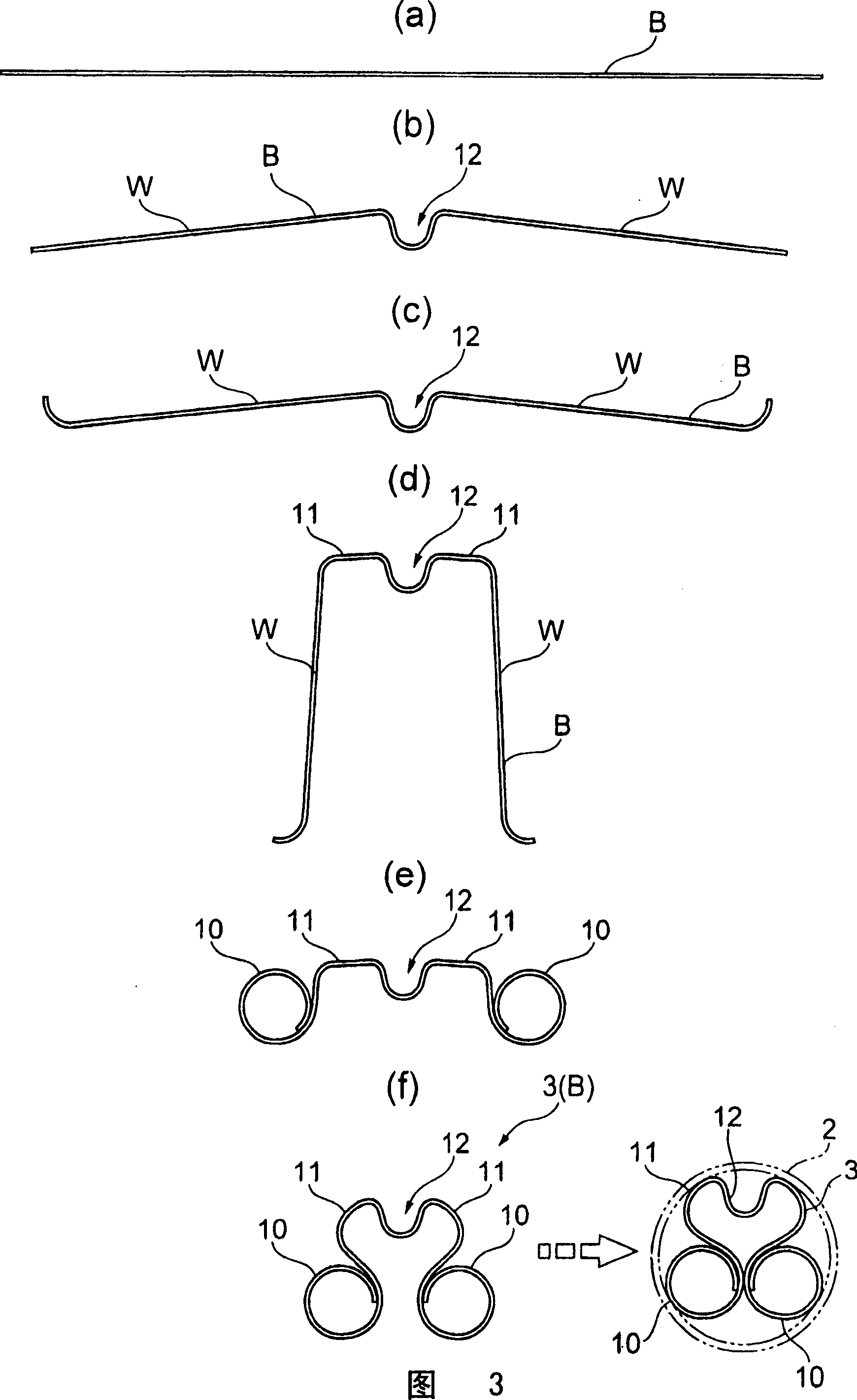
[0065] Furthermore, in the present embodiment, the core member 3 having such a spring action is formed by appropriately bending a single sheet metal material (referred to as mother plate material B). Specifically, the two ends of the motherboard material B are rounded into a circle so that the two ends can be elastically opened and closed (expanded), and the core member 3 is clamped by utilizin...

Embodiment 2

[0096] Embodiment 2 is an example in which the inserting and fixing of the core member 3 is realized based on the diameter reducing process (caulking process) performed on the outer cylindrical body 2 . As an example, caulking is carried out as shown in FIG. 8 by narrowing both ends of the opening of the outer cylindrical body 2 and the cylindrical portion (referred to here as a substantially central portion) over the entire circumference.

[0097] At this time, the caulking process of reducing the diameter of the opening ends of the outer cylinder 2 inwardly is performed only on the part of the outer cylinder 2 where the core 3 does not exist, and the deformation of the opening ends is utilized to seal from the left and right sides. The position (movement) of the core 3 is restricted, and the core 3 is fastened in the outer cylindrical body 2 . On the other hand, the caulking process of reducing the diameter of the cylindrical portion of the outer cylinder 2 inward is perform...


PUM


Abstract

A novel core piece for an exhaust gas catalyst device capable of realizing further reduction in weight, costs, etc. that are constantly demanded for automobile related components, a method of producing the core piece, and a method of inserting and fixing the core piece. A core piece (3) for an exhaust gas catalyst device (1), provided inside an outer tube body (2) into which an exhaust gas (G) issent and purifying the exhaust gas (G) by a catalyst adhered and formed on the surface of the core piece (3), wherein the core piece (3) is attached to the outer tube body (2) by at least either a method where the core piece (3) is formed so as to return elastically in the outer peripheral direction when the core piece (3) is deformed in the inner peripheral direction in attaching the core piece (3) to the outer tube body (2), and the core piece (3) is attached to the outer tube body (2) by spring elasticity of the core piece (3) itself, or a method where an appropriate portion of the outer tube (2), into which the core piece (3) is inserted, is reduced in diameter to attach the core piece (3) to the outer tube body (2).

Description

technical field [0001] The present invention relates to a device for purifying combustion gas exhausted from various internal combustion engines, and in particular to a core member provided inside an outer cylinder body and firmly installed in the outer cylinder body in a close-fit state, its manufacturing method and Its plug-in fixing method. Background technique [0002] Generally speaking, in an engine that obtains mechanical power by explosively burning oil in a pressure cylinder, the exhaust gas contains CO (carbon monoxide), HC (hydrocarbon), NO x (nitrogen oxides) and other harmful substances, so a catalyst device (purification device) that reduces such harmful substances is installed in the exhaust gas discharge path such as a muffler or an exhaust pipe. [0003] As such catalyst devices, there are, for example, Figure 14 (a) As shown in the integral type device, the core 3' having a honeycomb cross-section is embedded in the outer cylinder 2'. This device is to ma...

Claims


Application Information

Patent Timeline
IPC IPC(8): B01J35/02B01D53/86F01N3/28B01J32/00B21D53/84
CPCY02A50/20
Inventor 古桥义宏
Owner SAKURA IND
Learn More