
Horn mouth drum type screw wind power generator

A wind turbine and drum-type technology, which is applied to wind turbine components, wind turbines, wind turbine combinations, etc., can solve the problem that ordinary wind turbines occupy a large installation space, limit the application field of wind turbines, and reduce the size of wind turbines. Volume and other issues, to achieve the effect of improving performance and economic benefits, reducing volume, and reducing the space occupied by installation

Inactive Publication Date: 2007-01-24
单建锡
View PDF0 Cites 11 Cited by
  • Summary
  • Abstract
  • Description
  • Claims
  • Application Information

AI Technical Summary

Problems solved by technology

[0002] At present, ordinary wind generators are windmill-type large-blade wind generators with external blades, which cannot be used when the wind is small, and ordinary wind generators need to occupy a large installation space, which greatly limits the application field of wind generators; The Chinese invention patent declared by me on January 31, 2005 has disclosed "A Drum-type Spiral Wind Power Generator", refer to the attached image 3 , which greatly saves the installation space and reduces the volume of wind turbines, which can be applied to automobiles, trains, airplanes, ships and other motor vehicles
However, there is still a problem in the above-mentioned patent materials: since the outer cover is a straight cylindrical structure, the air intake volume is small, so the ambient wind speed required is relatively high to start generating electricity.

Method used


Image

  • Horn mouth drum type screw wind power generator
  • Horn mouth drum type screw wind power generator
  • Horn mouth drum type screw wind power generator

Examples


Embodiment 1

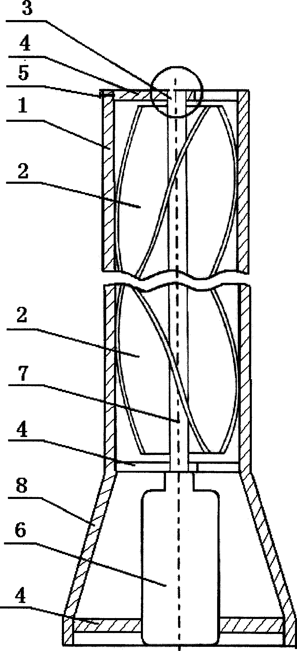
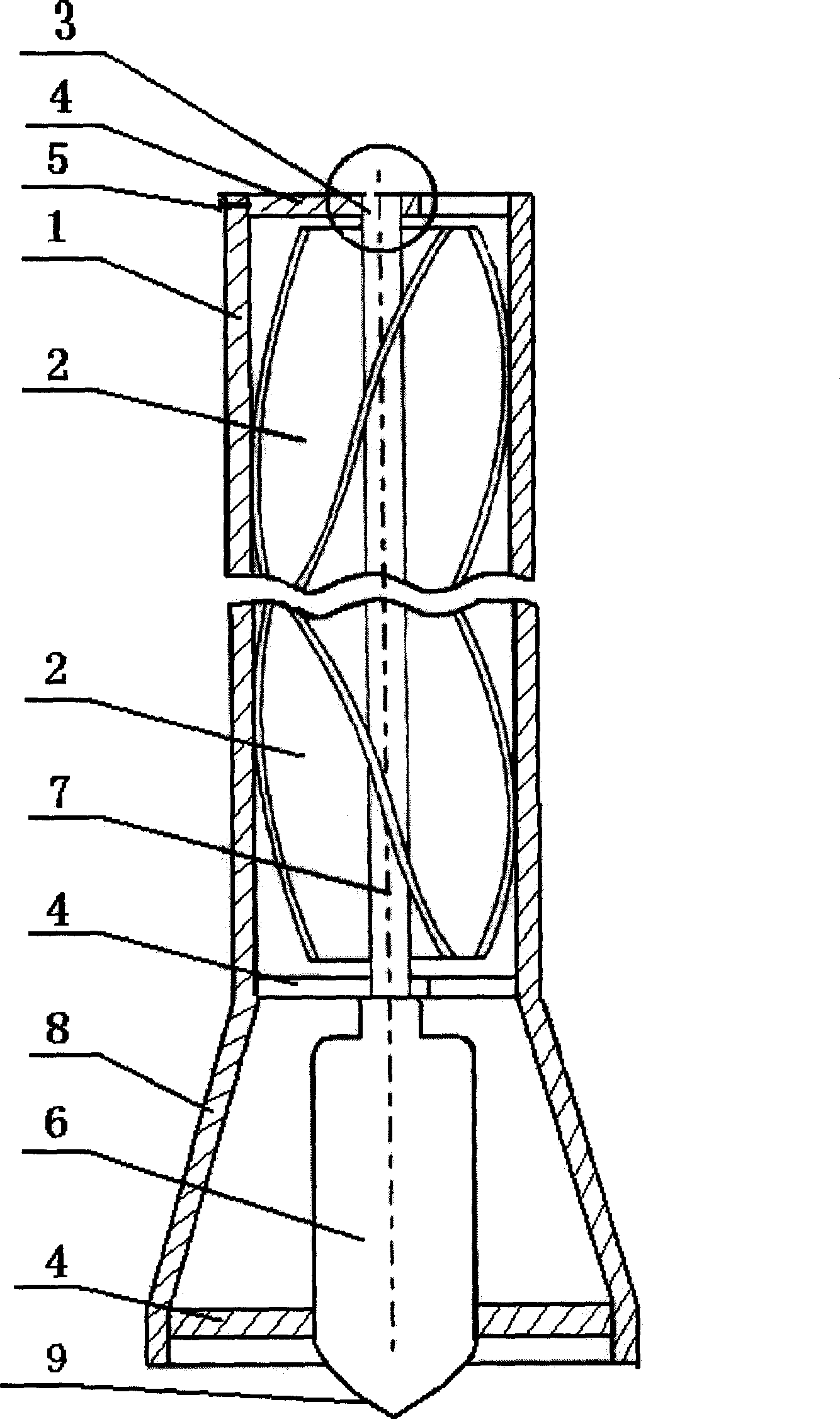
[0014] Embodiment 1, with reference to attached figure 1 , 3 , is mainly composed of an outer cover, a generator, blades and a transmission shaft. The upper part of the outer cover 1 is equipped with a spiral blade 2 and a deep groove ball bearing 3, and is connected to the outer cover 1 by bolts 5. The engine 6 and the bracket 4 are connected to form, the windward end of the outer cover 1 is set in the shape of a bell mouth, the generator 6 can be arranged in the bell mouth, and the spiral blade 2) is set in two or more pieces to form a group. . Refer to attached image 3 , the windward end of the generator 6 can be designed as a pyramidal structure 9 .

Embodiment 2

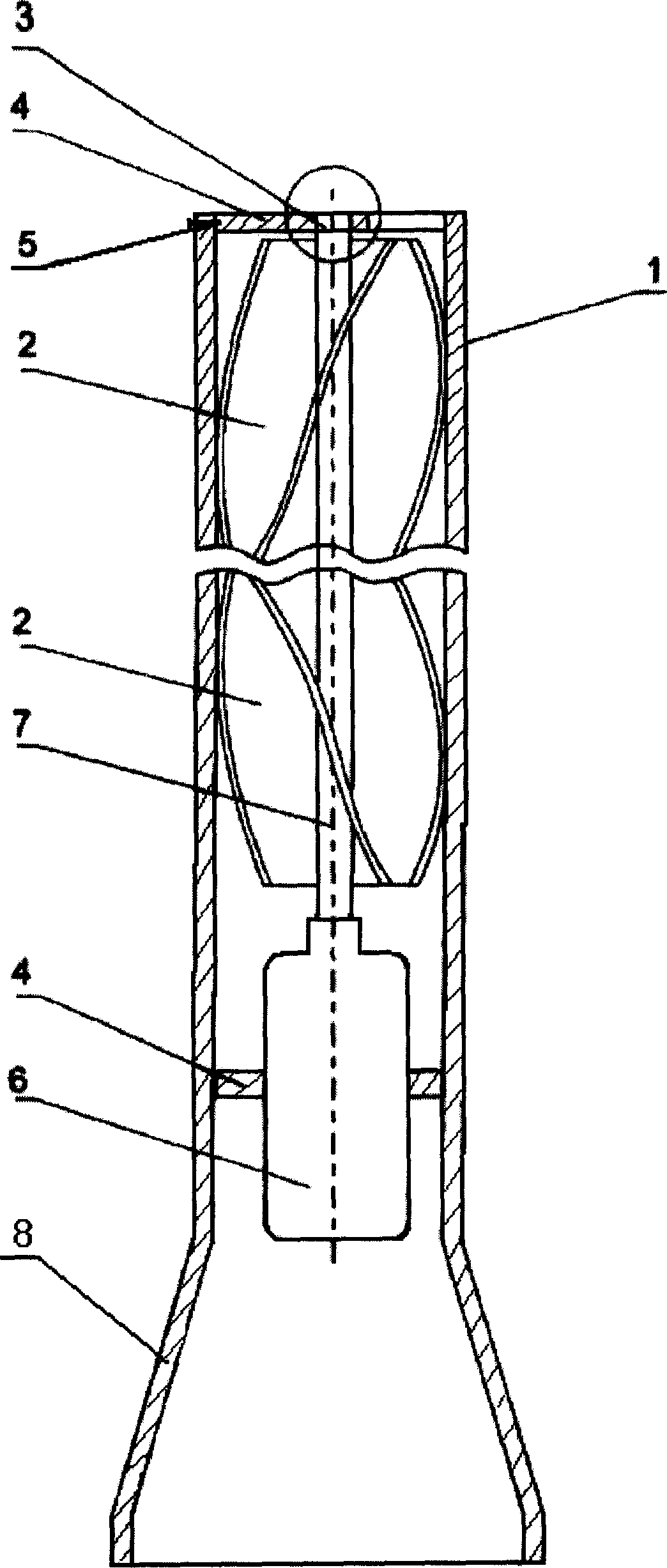
[0015] Embodiment 2, with reference to attached figure 2 , 4 , is mainly composed of an outer cover, a generator, blades and a transmission shaft. The upper part of the outer cover 1 is equipped with a spiral blade 2 and a deep groove ball bearing 3, and is connected to the outer cover 1 by bolts 5. Machine 6 and support 4 are connected to form, and the windward end of described outer cover 1 is set to trumpet shape, generator 6 can be arranged in the straight cylinder, and helical blade 2) is provided with two or more than two pieces to form a group. Refer to attached Figure 4 , the windward end of the generator 6 can be designed as a pyramidal structure 9 .

[0016] When in use, when the wind force reaches a certain speed, the required wind force is much lower than that of the original technology. The wind energy enters from the bell mouth, generates thrust in the sealed cylinder, drives the blades to rotate, and the rotation of the blades drives the generator, thereby ...


PUM


Abstract

The invention is especially related to drum type helix wind driven generator in shape of bell mouth applicable to car, train, airplane, and ship etc. Technical scheme is that the product is composed of outer cover, generator, blades, and transmission shaft; being installed on up part of the outer cover, helix type blades and trench type ball bearings through bolts are connected to the outer cover, and through transmission shaft are connected to generator and bracket at lower part; windward end of the outer cover is designed as shape of bell mouth; generator is positioned inside straight tube or inside bell mouth. Features are: reduced volume of generator compared under same power, and reduced space usage. Structure of bell mouth increases air input.

Description

1. Technical field: [0001] The invention relates to an electromechanical product utilizing wind power to generate electricity, in particular to a bell mouth drum type spiral wind power generator mainly used in automobiles, trains, airplanes, ships and other motor vehicles. 2. Background technology: [0002] At present, ordinary wind generators are windmill-type large-blade wind generators with external blades, which cannot be used when the wind is small, and ordinary wind generators need to occupy a large installation space, which greatly limits the application field of wind generators; The Chinese invention patent declared by me on January 31, 2005 has disclosed "A Drum-type Spiral Wind Power Generator", refer to the attached image 3 , greatly saving the installation space, reducing the size of the wind turbine, and can be applied to automobiles, trains, airplanes, ships and other motor vehicles. However, there is still a problem in the above-mentioned patent materials: si...

Claims


Application Information

Patent Timeline
Patent Type & Authority Applications(China)
IPC IPC(8): F03D9/00F03D11/04F03D3/06H02K5/04F03D9/25F03D13/20F03D80/70
CPCY02E10/728Y02E10/74
Inventor 单建锡
Owner 单建锡
Learn More