
Tube plate condenser for refrigerators and/or freezers

A refrigeration device and refrigeration device technology, which is applied in the direction of evaporator/condenser, refrigeration and liquefaction, refrigerator, etc., and can solve problems such as heat dissipation limitations

Inactive Publication Date: 2007-01-24
利布赫尔家用器具奥克森豪森有限责任公司
View PDF1 Cites 1 Cited by
  • Summary
  • Abstract
  • Description
  • Claims
  • Application Information

AI Technical Summary

Problems solved by technology

However, the heat dissipation is still limited, and therefore still requires maintaining a considerable surface and tube length for the load-bearing panels

Method used


Image

  • Tube plate condenser for refrigerators and/or freezers
  • Tube plate condenser for refrigerators and/or freezers
  • Tube plate condenser for refrigerators and/or freezers

Examples


Embodiment Construction

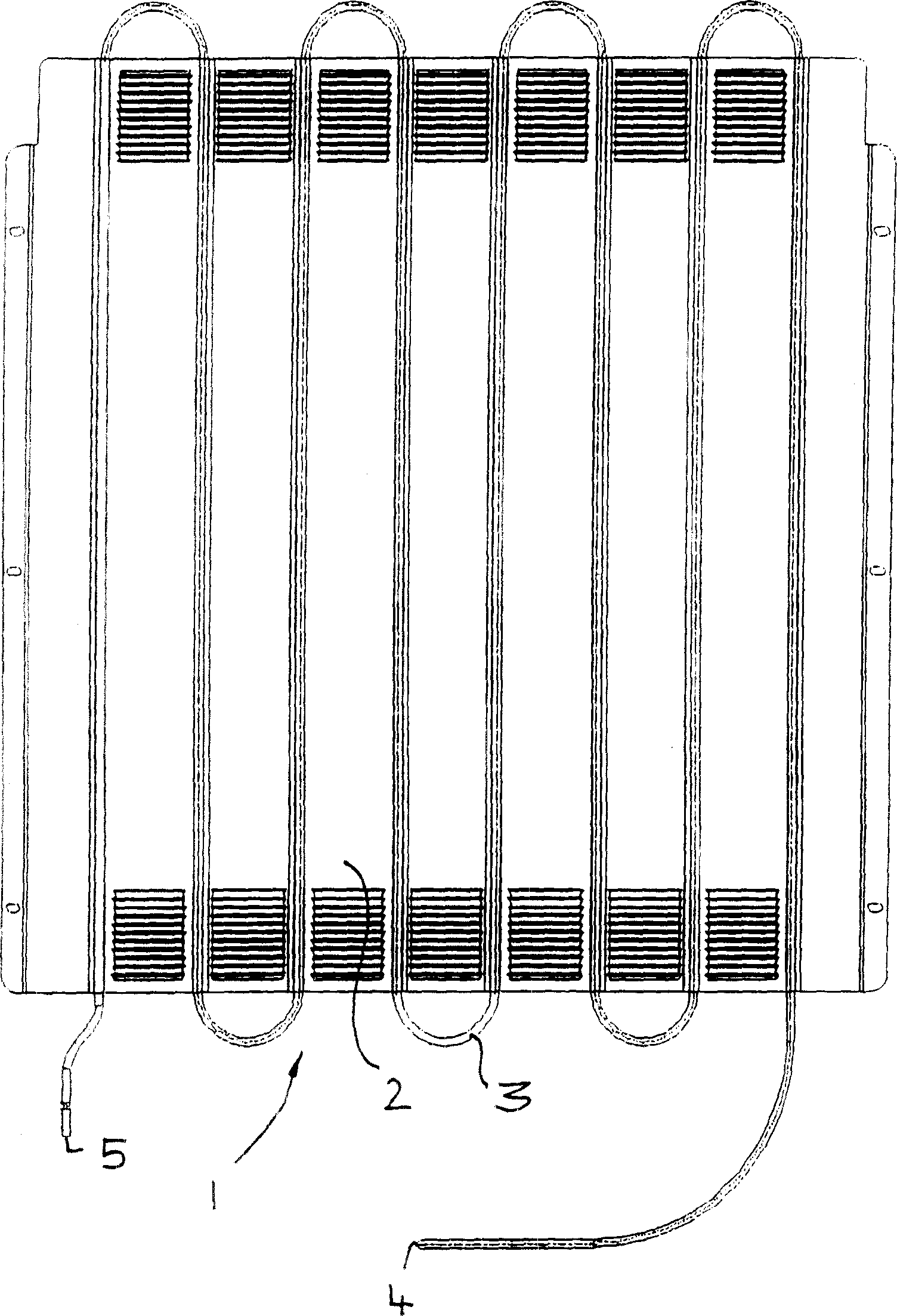
[0017] figure 1 The illustrated condenser 1 comprises a substantially plate-shaped carrier panel 2 and a condenser tube 3 connected thereto, which extends back and forth in a serpentine bend and has an inlet 4 and an outlet 5 . When the refrigerant flows through the condenser tubes extending in a serpentine manner, the refrigerant releases absorbed heat to the bearing panel 2 through the condenser tube 3, and releases heat to the surrounding environment through the bearing panel 2, so the evaporator medium or the The refrigerant is cooled down and condensed again until it is reintroduced via outlet 5 to subsequent functional units of the refrigeration circuit.

[0018] The bearing panel 2 is made of aluminum or aluminum alloy sheet metal. According to an embodiment of the present invention, the condenser tube 3 is similarly constructed of aluminum or an aluminum alloy. Alternatively, steel pipes can be used as condenser tubes 3, which steel pipes can be galvanized according ...


PUM


Abstract

The present invention relates to a tube / plate condenser for a cooling circuit of a refrigerator and / or freezer comprising a bent tube in which the cooling circuit medium can be condensed as well as a carrier panel of sheet metal to which the tube is secured. In accordance with the invention, the tube / plate condenser is characterized in that the carrier panel consists of an aluminum sheet and the tube is a steel tube. The present invention further relates to a refrigerator and / or freezer comprising a tube / plate condenser of this type.

Description

technical field [0001] The invention relates to a tube-sheet condenser for a cooling circuit of a refrigerating device and / or a freezing device, comprising tubes, preferably bent into a serpentine shape, in which the cooling circuit medium condenses, and also comprising a tube made of sheet metal A finished load-bearing panel to which the tube is secured. Background technique [0002] Tube-sheet condensers of this type for refrigeration and / or freezer installations are known, for example, from DE 20 2004 017 652 U1. The rear wall of this type of condenser usually consists of a steel panel on which steel pipes bent in a serpentine shape are installed and fixed, both steel panels and steel pipes being painted. Since heat dissipation is limited for this type of condenser, the tubes bent in a serpentine shape must have a correspondingly large length, and the carrying panels made of sheet metal for dissipation of the heat into the surrounding environment must There is a corresp...

Claims


Application Information

Patent Timeline
Patent Type & Authority Applications(China)
IPC IPC(8): F25B39/04
Inventor T·布勒施
Owner 利布赫尔家用器具奥克森豪森有限责任公司
Learn More